John Deere 318 User Manual
Page 235
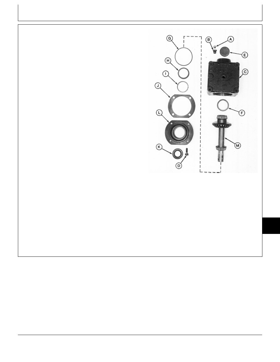
5. Install new bearing cup (F), if removed, using a driver
set.
6. Press plug (E) into gear case (C) with lip facing away
from gear case. Install plug until recessed 1.59 mm
(0.062 in.) below gear case surface.
7. Install adapter (B) and vent plug (A).
8. Press new seal (K) into retainer (L) until top of seal is
recessed 2.54 mm (0.100 in.) below retainer surface.
9. Apply multipurpose grease to lip of seal.
IMPORTANT: A new crush ring must be installed
during assembly. The ring collapses
when retainer is tightened to gear case
to achieve proper output shaft end
play.
10. Install new crush ring (I) and bearing cup (H).
11. Install shim (J) and new O-ring (G).
IMPORTANT: Tape end of output shaft to prevent
seal damage during shaft installation.
Output Shaft Side
12. Apply tape around end of output shaft.
13. Assemble output shaft assembly (M) and retainer (L).
A—Vent Plug
Remove tape.
B—Adapter
C—Gear Case
D—Cap Screw (4 used)
14. Install retainer and output shaft assembly into gear
E—Plug
case (C).
F—Bearing Cup
G—O-Ring
15. Install four cap screws (D) and tighten to 30 N·m (22
H—Bearing Cup
lb-ft).
I—Crush Ring
J—Shim (as required)
K—Seal
L—Retainer
M—Output Shaft Assembly
M77319
-UN
-24FEB95
MX,15908015,7 -19-13MAR95
Mower Gear Case Repair/50-Inch Mower
TM1590 (17MAY95)
80-15-7
316, 318 & 420 Lawn and Garden Tractors
020895
80
15
7