John Deere 318 User Manual
Page 80
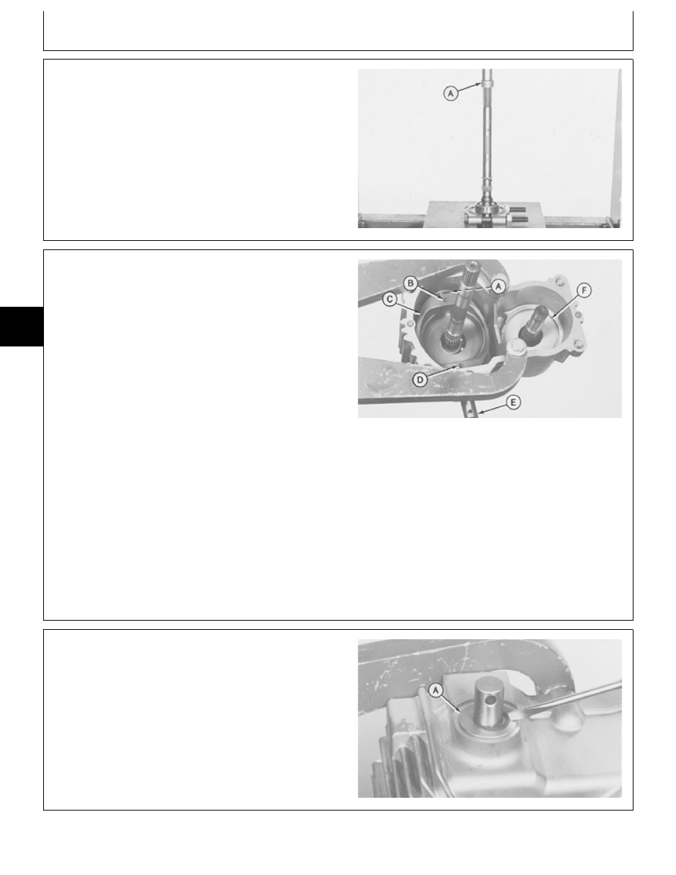
6. Push pump shaft into bearing until it is on the shaft
shoulder using a 1-in. driver disk (A) bearing puller
attachment and a press.
M36130
-UN
-29AUG88
NOTE: Tape over splines to protect seals from possible
damage when installing shafts, remove tape after
installation.
7. Install pump shaft.
8. Install swashplate (C), control shaft (E), and shaft (A).
IMPORTANT: Pump shaft and bearing assembly
could restrict movement of swashplate.
Full swashplate movement is
approximately 25 mm (1 in.) each
direction. If necessary tap shaft with a
soft faced hammer to seat bearing.
A—Trunnion Shaft
B—Spring Pin
9. Drive pin (B) into swashplate and shaft until pin is
C—Pump Swashplate
about 6 mm (1/4 in.) below swashplate surface.
D—Spring Pin (2 used)
E—Control Shaft
10. Drive two pins (D) into swashplate and control shaft
F—Motor Housing
until top pin is about 6 mm (1/4 in.) below swashplate
surface.
M36525
-UN
-25JAN90
11. Install washer (A) and snap ring on trunnion and
control shaft.
12. Remove housing from bench fixture.
M36526
-UN
-25JAN90
M45,5005A,69 -19-13MAR85
MX,15905005,26 -19-23FEB95
5M3,5005K,AF -19-18DEC87
Transmission/Assemble
TM1590 (17MAY95)
50-05-20
316, 318 & 420 Lawn and Garden Tractors
020895
50
05
20