Theory of operation, Group 15 – John Deere 318 User Manual
Page 423
HYDRAULIC LIFT SYSTEM
OPERATION—THREE-POSITION SPOOL
Function:
To control the flow of pressurized oil to the rockshaft
cylinder or implement.
Theory of Operation:
NOTE: Lower position shown.
On later 318 and 420 models, pressurized oil is
routed through the steering valve before reaching
the hydraulic control valve. This design provides
“power beyond” to the auxiliary hydraulic systems
only after satisfying steering valve needs. (See
Section 260 for further information.)
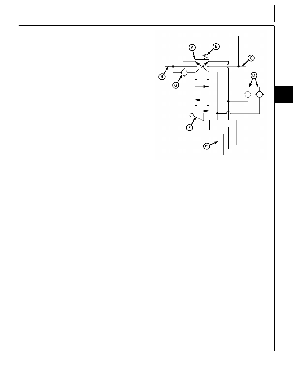
LOWER:
As the handle is moved to the LOWER position, linkage
connected to the actuator (F) causes the control valve
spool (A) to change position. Pressurized oil entering the
control valve inlet (H) forces the check valve (G) to
open. Oil is then directed by the spool valve to the
rockshaft cylinder (E) or hydraulic outlets (D).
A—Control Valve Spool
B—Centering Spring
Oil returning from the cylinder or implement is routed
C—Return Oil to Transmission
through the control valve spool and is returned to the
D—Hydraulic Outlets
transmission.
E—Rockshaft Cylinder
F—Actuator
G—Check Valve
RAISE:
H—Control Valve Inlet
Valve operation for RAISE is similar to LOWER, except
that spool position reverses oil flow.
NEUTRAL:
As the handle is released, the centering spring (B)
returns the control valve spool (A) to the neutral position.
Oil flow to/from the cylinder or implement is then
blocked, holding the implement in either the raised or
lowered position.
The valve spool position allows pressurized oil to flow
through the valve to other valves in the system, or return
to the transmission.
M78849
-UN
-03APR95
MX,159027015,1 -19-03MAY95
Group 15
Theory of Operation
TM1590 (17MAY95)
270-15-1
316, 318 & 420 Lawn and Garden Tractors
020895
270
15
1