John Deere 318 User Manual
Page 326
2j
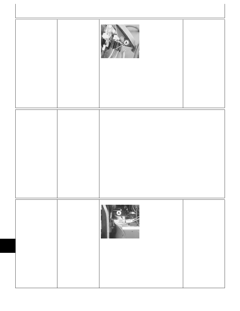
Starter Circuit
Test at PTO Switch
Turn key switch to RUN
position.
M55146 -UN-11DEC89
Check for voltage at
terminal (A) with yellow
and purple wires, then
at terminal with single
purple wire.
VOLTAGE ONE
TERMINAL: Replace
switch.
VOLTAGE BOTH
TERMINALS: Purple
wire between jumper
connector and PTO
switch is open.
NO VOLTAGE: GO TO
1e
Repair or replace wire,
then GO TO
‘
, Group
05.
Æ
IGNITION CIRCUIT
TESTS
Listed at right are
symptoms that may
occur in a
malfunctioning ignition
circuit. Locate the
symptom that applies,
then proceed to the
appropriate test.
IGNITION CIRCUIT SYMPTOMS:
—Starter Cranks Engine
Satisfactorily, But Engine
Doesn’t Start: GO TO
3a
—Engine Stops With Operator
On Seat When:
PTO Switch Is Turned On,
Or
Hydrostatic Lever Is Moved
To Forward Or Reverse Position,
Or
Brake Pedal Is Released
(Later Machines Only).
GO TO
4e
—Engine Starts, But Misfires:
For Machines (S.N. —420000);
GO TO
3j
For Machines (S.N. 420001— );
GO TO
3k
3a
Ignition Circuit
Test—All Machines
PTO switch OFF.
Hydrostatic lever in
N/STOP position.
NOTE: Engaged park
brake required on
machines:
316 (S.N. 596121— )
318 (S.N. 600305— )
420 (S.N. 595881— )
Engage park brake.
M55081 -UN-17JAN95
Remove right-hand
engine side panel.
Disconnect engine 3-pin
connector.
Turn key switch to RUN
position.
Check for voltage at
pink wire terminal of
connector (A).
VOLTAGE:
For Machines
(S.N. —420000);
GO TO
3b
For Machines
(S.N. 420001— );
GO TO
3f
NO VOLTAGE:
GO TO
3l
MX,159024025,39-19-16MAY95
MX,159024025,40-19-16MAY95
MX,159024025,41-19-16MAY95
Electrical System Diagnosis/Ignition Circuit Tests
TM1590 (17MAY95)
240-20-14
316, 318 & 420 Lawn and Garden Tractors
020895
240
20
14