John Deere 318 User Manual
Page 159
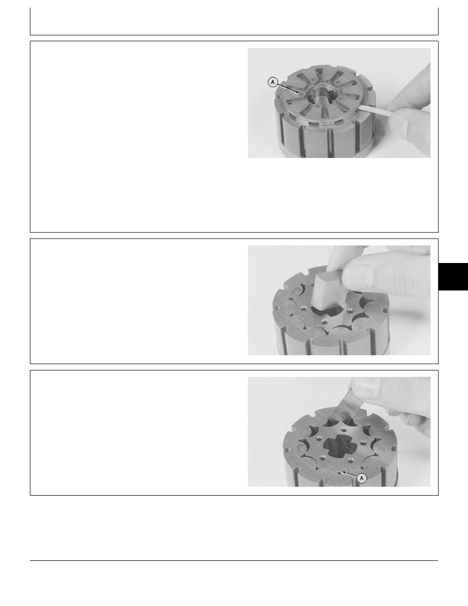
IMPORTANT: DO NOT use a screwdriver to remove
commutator. Commutator can be
damaged.
27. Remove commutator and five pins (A) using a wood
dowel or equivalent.
NOTE: The commutator is made up of two plates
bonded together. It is a permanent assembly and
cannot be disassembled.
28. Check commutator machined surface, holes and
edges for nicks. Edges must be sharp.
M36848
-UN
-29AUG88
29. Remove drive link spacer. Check spacer for grooves,
wear, or damage.
30. The rotor should rotate and orbit freely within the
stator. Check commutator side of stator face for grooves
or scoring.
NOTE: Stator and rotor are a matched set. If either are
worn or damaged, both must be replaced.
M36849
-UN
-29AUG88
31. Measure rotor-to-stator clearance. Center rotor lobe
(A) between stator lobes and check clearance directly
opposite lobe (A).
If rotor-to-stator clearance is more than 0.08 mm (0.003
in.), replace rotor and stator.
M36850
-UN
-29AUG88
MX,15906006,21 -19-01MAR95
MX,15906006,22 -19-01MAR95
MX,15906006,23 -19-01MAR95
Steering—318 and 420/Steering Valve
TM1590 (17MAY95)
60-06-9
316, 318 & 420 Lawn and Garden Tractors
020895
60
06
9