John Deere 318 User Manual
Page 232
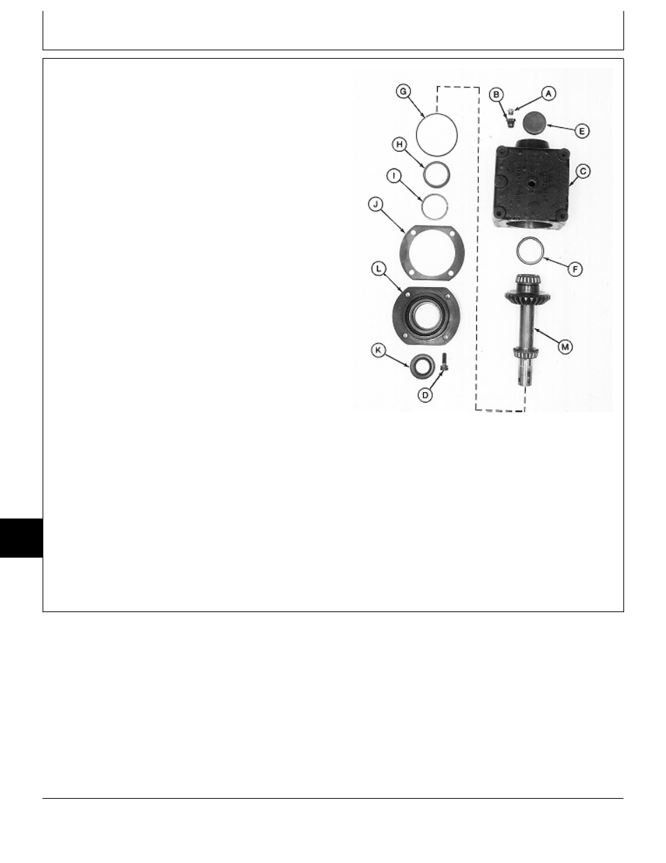
12. Remove vent plug (A) and adapter (B) from gear
case (C).
13. Remove four cap screws (D). Remove retainer (L)
and output shaft assembly (M).
14. Remove output shaft assembly (M) from retainer (L).
IMPORTANT: Remove and discard crush ring (I). A
new crush ring must be installed
during assembly to achieve proper
output shaft end play.
15. Remove O-ring (G), shim (J), bearing cup (H) and
crush ring (I). Discard crush ring.
16. Press out seal (K) from retainer (L).
NOTE: Bearing cup (F) and plug (E) are press-fit in gear
case. Remove bearing cup (F) only if
replacement is necessary.
Bearing cones and cups are matched and must
be replaced as complete assemblies.
17. Inspect bearing cups (F and H) for wear or damage.
Replace as necessary.
Output Shaft Side
18. Press out plug (E) and bearing cup (F).
A—Vent Plug
B—Adapter
C—Gear Case
D—Cap Screw (4 used)
E—Plug
F—Bearing Cup
G—O-Ring
H—Bearing Cup
I—Crush Ring
J—Shim (as required)
K—Seal
L—Retainer
M—Output Shaft Assembly
M77319
-UN
-24FEB95
MX,15908015,4 -19-29MAR95
Mower Gear Case Repair/50-Inch Mower
TM1590 (17MAY95)
80-15-4
316, 318 & 420 Lawn and Garden Tractors
020895
80
15
4