John Deere 318 User Manual
Page 244
IMPORTANT: Tape end of output shaft to prevent
seal damage during shaft installation.
11. Apply tape around end of output shaft.
12. Assemble output shaft assembly and cap (B).
Remove tape.
NOTE: Flat sides of cap must align with flat sides of
gear case. Gear case mounting surface must be
flat to install gear case on mower deck.
13. Install shims (D). Align marks made during
disassembly and install output shaft assembly into gear
case (C).
14. Install four cap screws and lock plates (A) and
tighten to 30 N·m (22 lb-ft).
15. Check output shaft endplay. Endplay should be
within 0.025—0.076 mm (0.001—0.003 in.). If necessary,
remove cap and output shaft assembly and add or
remove shims (D) as needed.
16. Again, remove four cap screws and lock plates (A)
and cap and output shaft assembly.
Output Shaft Side
17. Clean mating surfaces of cap, shims and gear case
using Clean and Cure Primer. Apply a bead of
Form-In-Place Gasket, or an equivalant, between inside
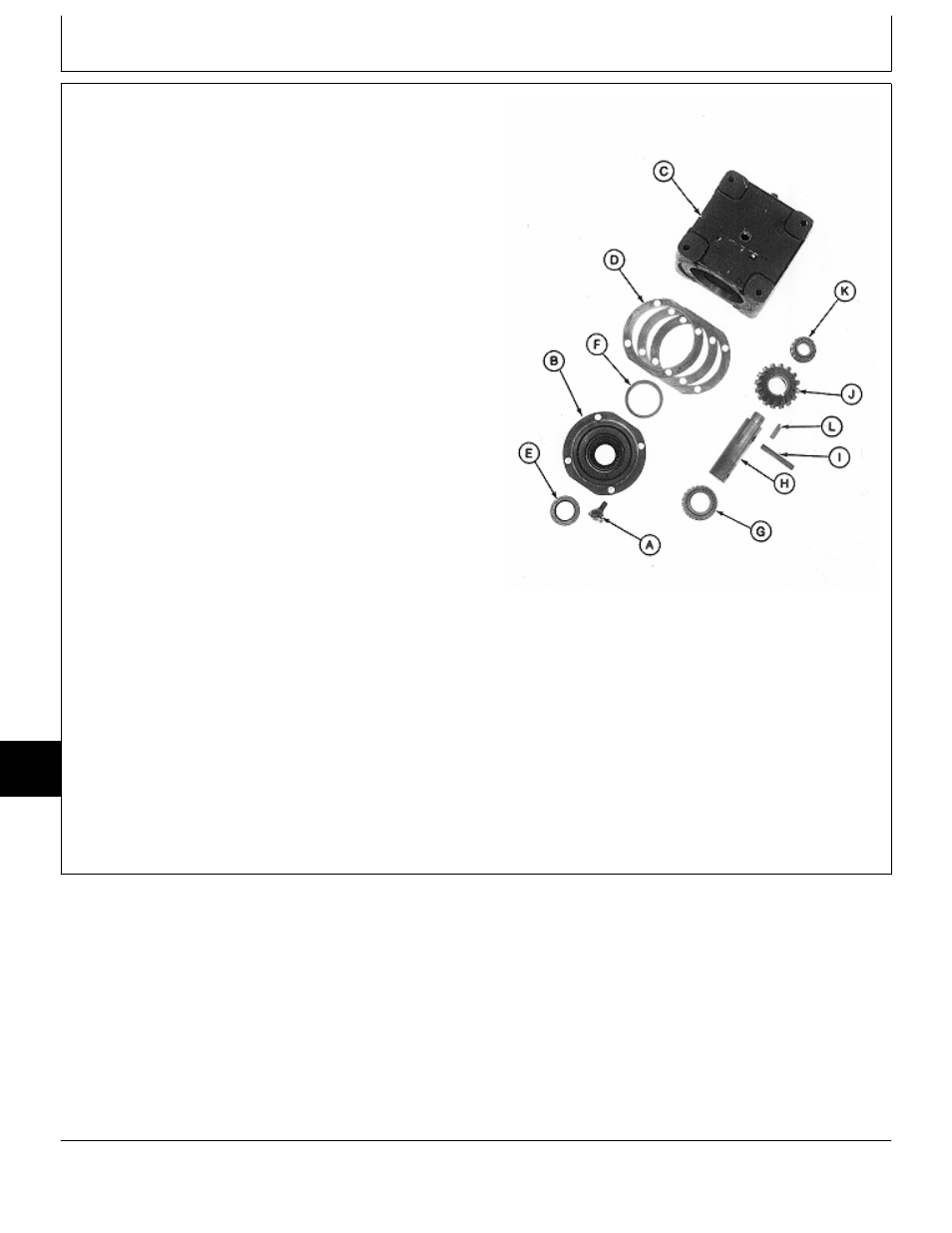
A—Cap Screw and Lock Plate (4 used)
edge of top shim and lip on cap (B).
B—Cap
C—Gear Case
D—Shims (as required)
18. Align and install cap and output shaft assembly into
E—Seal
gear case. Install four cap screws and lock plates (A)
F—Bearing Cup
and tighten to 30 N·m (22 lb-ft). Bend lock plates up
G—Bearing Cone
around cap screws.
H—Output Shaft
I—Spring Pin
J—Bevel Gear
K—Bearing Cone
L—Key
M77330
-UN
-24FEB95
MX,15908015,39 -19-13MAR95
Mower Gear Case Repair/Early 60-Inch Mower (Curtis)
TM1590 (17MAY95)
80-15-16
316, 318 & 420 Lawn and Garden Tractors
020895
80
15
16