Electrical system checkout, Before you start, Group 05 – John Deere 318 User Manual
Page 287
BEFORE YOU START
Always begin with this group to identify a failure in
the electrical system. The step-by-step procedures will
provide you with a quick check of the system. No
special tools are required to perform these checks. If
a failure is indicated, you will be referred to a more
detailed check, adjustment, or test located in Groups
20 and 25.
Always start with the first step and follow the
sequence from left to right. Read each step
completely before performing the check.
This procedure is designed as a quick check of the
system. Concentrate only on the check being
performed and disregard signals from unrelated
components. If unfamiliar with the operation or
location of system components, refer to Group 15 in
this section.
NOTE: For clarity in this section, machines before the
serial number listed below will be referred to
as “Early Models”. Machines including and
after serial numbers listed below will be
referred to as “Later Models”.
316 (S.N. 596121— )
318 (S.N. 600305— )
420 (S.N. 595881— )
Later model machines have a brake switch
added to the neutral start circuit, which is
activated by the brake pedal(s).
;
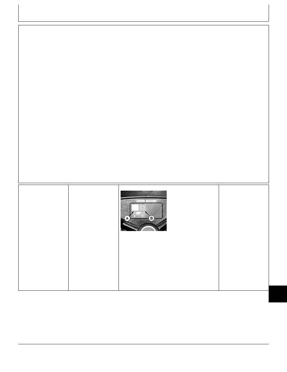
DASH LAMP
CIRCUIT CHECK
NOTE: The following
checks apply to the
battery discharge and
oil pressure lamps only.
To check the PTO
lamps, GO TO
Å
PTO switch OFF.
Turn key switch to RUN
position.
M55028 -UN-13APR95
LOOK: Battery
discharge light (B) must
come ON once, then
go OFF.
NOTE: If battery
voltage is low, lamp
may stay ON.
LOOK: Oil pressure
lamp (A) must be ON.
OK:
GO TO
‘
NOT OK:
GO TO
1a
MX,159024005,1 -19-16MAY95
MX,159024005,2 -19-16MAY95
Group 05
Electrical System Checkout
TM1590 (17MAY95)
240-05-1
316, 318 & 420 Lawn and Garden Tractors
020895
240
05
1