Overview, Cascadeable ez-screen, Warning – Banner EZ-SCREEN Safety Light Curtain Systems User Manual
Page 66
64
P/N 133487
Banner Engineering Corp.
•
Minneapolis, U.S.A.
www.bannerengineering.com
•
Tel: 763.544.3164
Overview
64
Banner Engineering Corp.
•
Minneapolis, U.S.A.
www.bannerengineering.com
•
Tel: 763.544.3164
EZ-SCREEN
Instruction Manual
Cascadeable EZ-SCREEN
Monitoring Series-Connected Positive-Opening Safety Switches
When monitoring two individually mounted safety switches (as
shown in Figure 7-9), a faulty switch will be detected if it fails
to switch as the guard opens. In this case, the EZ-SCREEN
will de-energize its OSSD output and disable its reset function
until the input requirements are met (i.e., the faulty switch
is replaced). However, when a series of interlocking safety
switches is monitored by the EZ-SCREEN, the failure of one
switch in the system may be masked or not detected at all (refer
to Figure 7-10).
Series-connected, positive-opening interlock switch circuits do
not meet ISO 13849-1 Safety Category 4 and may not meet
Control Reliability requirements because of the potential of
an inappropriate reset or a potential loss of the safety stop
signal. A multiple connection of this type should not be used
in applications where loss of the safety stop signal or an
inappropriate reset could lead to serious injury or death. The
following two scenarios assume two positive-opening safety
switches on each guard:
1. Masking of a failure. If a guard is opened but a switch fails
to open, the redundant safety switch will open and cause the
EZ-SCREEN to de-energize its outputs. If the faulty guard
is then closed, both Cascade input channels also close, but
because one channel did not open, the EZ-SCREEN will not
reset.
However, if the faulty switch is not replaced and a second
“good” guard is cycled (opening and then closing both of
the cascade input channels), the EZ-SCREEN considers the
failure to be corrected. With the input requirements apparently
satisfied, the EZ-SCREEN allows a reset. This system is no
longer redundant and, if the second switch fails, may result in
an unsafe condition (i.e., the accumulation of faults results in
the loss of the safety function).
2. Non-detection of a failure. If a good guard is opened, the
EZ-SCREEN de-energizes its outputs (a normal response).
But if a faulty guard is then opened and closed before the
good guard is re-closed, the failure on the faulty guard is not
detected. This system also is no longer redundant and may
result in a loss of safety if the second safety switch fails to
switch when needed.
The circuits in either scenario do not inherently comply with
the safety standard requirements of detecting single faults and
preventing the next cycle. In multiple-guard systems using series-
connected positive-opening safety switches, it is important to
periodically check the functional integrity of each interlocked
guard individually. Operators, maintenance personnel, and
others associated with the operation of the machine must
be trained to recognize such failures and be instructed to
correct them immediately.
Open and close each guard separately while verifying that the
EZ-SCREEN outputs operate correctly throughout the check
procedure. Follow each gate closure with a manual reset, if
needed. If a contact set fails, the EZ-SCREEN will not enable its
reset function. If the EZ-SCREEN does not reset, a switch may
have failed; that switch must be immediately replaced.
This check must be performed and all faults must be cleared, at
a minimum, during periodic checkouts. If the application can
not exclude these types of failures and such a failure could
result in serious injury or death, then the safety switches
must not be connected in series.
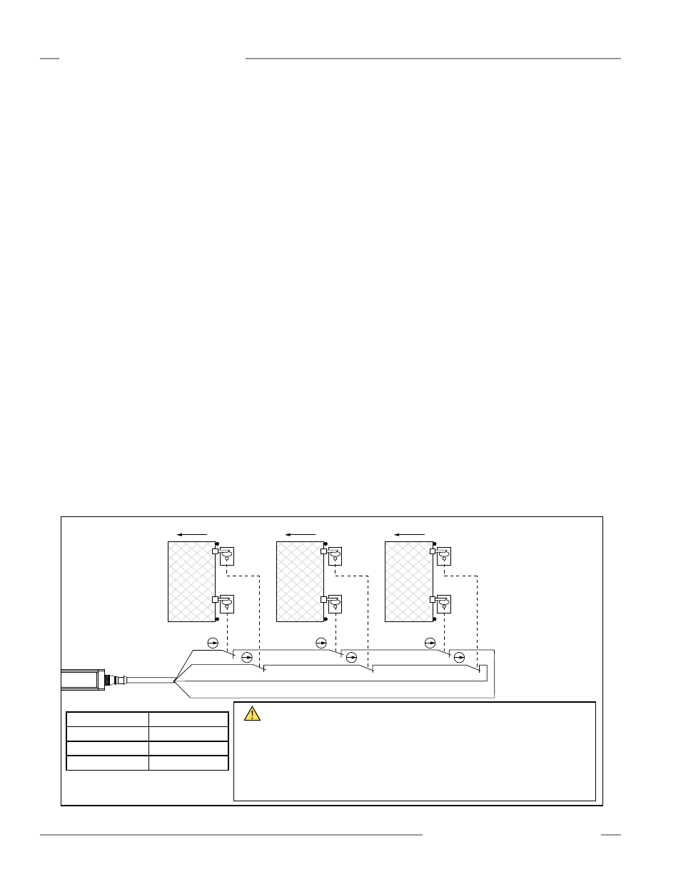
Figure 7-10. Monitoring positive-opening safety switches on multiple gates
WARNING . . .
Not a Safety Category 4 Application
When monitoring multiple guards with a series connection of multiple safety interlock switches,
a single failure may be masked or not detected at all.
When such a configuration is used, procedures must be performed regularly to verify proper
operation of each switch. See “Monitoring Series-Connected Positive-Opening Safety Switches”
(Section 7.9.1) for more information. Failure to do so could result in serious injury or death.
* Standard M12 / Euro-style cables (8-pin male QD)
can also be used, although pin number / wire color
must be verified.
Wh
Open
Bk
Bn
QDE2R4-8..D Cable Pinout*
Pin #1 ― Brown (Ch 1a) Pin #5 ―n.c.
Pin #2 ― Black (Ch 1b)
Pin #6 ―n.c.
Pin #3 ― Blue (Ch 2b)
Pin #7 ―n.c.
Pin #4 ―n.c.
Pin #8 ― White (Ch 2a)
Bu
Open
Open