Overview, Components and specifications, 3 cables – Banner EZ-SCREEN Safety Light Curtain Systems User Manual
Page 11
P/N 133487
9
Banner Engineering Corp.
•
Minneapolis, U.S.A.
www.bannerengineering.com
•
Tel: 763.544.3164
Overview
P/N 112852 rev. F
9
Banner Engineering Corp.
•
Minneapolis, U.S.A.
www.bannerengineering.com
•
Tel: 763.544.3164
EZ-SCREEN
Instruction Manual
9
Banner Engineering Corp.
•
Minneapolis, U.S.A.
www.bannerengineering.com
•
Tel: 763.544.3164
Banner Engineering Corp.
•
Minneapolis, U.S.A.
www.bannerengineering.com
•
Tel: 763.544.3164
Components and Specifications
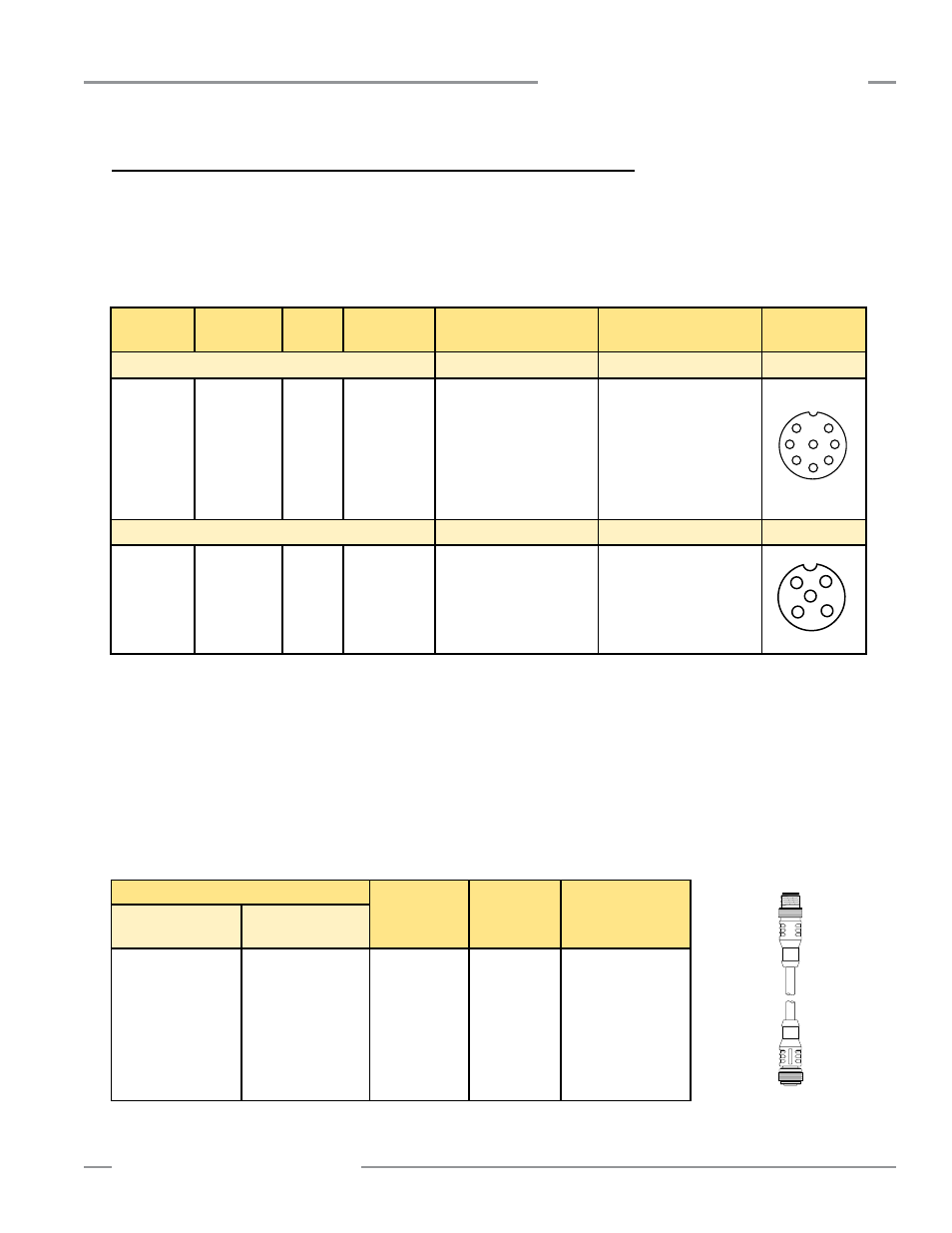
2.3 Cables
Machine interface cables provide power to the first emitter/receiver pair. Sensor interconnect
cables provide power to subsequent emitters and receivers in the cascade.
Single-Ended (Machine Interface) Cables (one cable for each emitter and receiver)
Overmold and cables are PVC-jacketed. Cables are unterminated on one end to interface
with guarded machine.
* The European M12 Specification pin assignment and color codes are listed as a customer courtesy. The user must verify suitability of these
cables for each application.
** 8-pin Systems require two 8-pin QD cables. Only pins 1, 6, and 7 are connected on 8-pin emitters (see Figure 3-16).
*** 5-pin EZ-SCREEN emitter, model numbers SLSE..-..Q5 (see Table 2.1) with Test function (see Figure 3-17). One 5-pin and one 8-pin
QD cable required for complete system.
Model
Number
Length
Wire
Termination
Banner Cable
Pinout/Color Code
European M12
Specification*
Connector
(female face view)
For 8-Pin Emitters and Receivers**
Pin Color Function
Pin Color Function
QDE-815D
QDE-825D
QDE-850D
QDE-875D
QDE-8100D
4.5 m (15')
8 m (25')
15 m (50')
23 m (75')
30 m (100')
22
gauge
8-pin Euro-
style female
connector on
one end; cut
to length
1
Bn
+24V dc
2
Or/Bk EDM #2 (Aux)
3
Or
EDM #1
4
Wh
OSSD #2
5
Bk
OSSD #1
6
Bu
0V dc
7
Gn/Ye Gnd/Chassis
8
Vi
Reset
1 Wh
+24V dc
2 BN
EDM #2 (Aux)
3 Gn
EDM #1
4 Ye
OSSD #2
5 Gy
OSSD #1
6 Pk
0V dc
7 Bu
Gnd/Chassis
8 Rd
Reset
For 5-Pin Emitters and Receivers***
Pin Color Function
Pin Color Function
QDE-515D
QDE-525D
QDE-550D
QDE-575D
QDE-5100D
4.5 m (15')
8 m (25')
15 m (50')
23 m (75')
30 m (100')
22
gauge
5-pin Euro-
style female
connector on
one end; cut
to length
1
Bn
+24V dc
2
Wh
Test #2
3
Bu
0V dc
4
Bk
Test #1
5
Gn/Ye Gnd/Chassis
1 Bn
+24V dc
2 Wh
Test #2
3 Bu
0V dc
4 Bk
Test #1
5 Shield Gnd/Chassis
1
7
6
5
4
3
2
8
1
2
3
4
5
Double-Ended (Sensor Interconnect) Cables
Double-ended cables are generally used to interconnect multiple emitters (8-pin or 5-pin)
or receivers (8-pin) within a cascaded system. They are also useful for extending either
the branch or trunk cables of a model CSB splitter cordset (see page 10). When combining
cables in a multiple-light-screen cascade, refer to Section 7.4 for maximum cable lengths.
Model Number
Length
Wire
Termination
For 8-Pin Emitters
and Receivers
For 5-Pin Emitters
DEE2R-81D
DEE2R-83D
DEE2R-88D
DEE2R-815D
DEE2R-825D
DEE2R-850D
DEE2R-875D
DEE2R-8100D
DEE2R-51D
DEE2R-53D
DEE2R-58D
DEE2R-515D
DEE2R-525D
DEE2R-550D
DEE2R-575D
DEE2R-5100D
0.3 m (1')
1 m (3')
2.4 m (8')
4.5 m (15')
8 m (25')
15 m (50')
23 m (75')
30 m (100')
22 gauge
5- or 8-pin
Double-ended
cables, M12/Euro-
style connectors,
female to male
(rotateable)