Overview, Installation and alignment, 6 preparing for system operation – Banner EZ-SCREEN Safety Light Curtain Systems User Manual
Page 40: Emitter (standard) emitter (with test), Ez-screen instruction manual, Mini-screen, And micro-screen
38
P/N 133487
Banner Engineering Corp.
•
Minneapolis, U.S.A.
www.bannerengineering.com
•
Tel: 763.544.3164
Overview
38
Banner Engineering Corp.
•
Minneapolis, U.S.A.
www.bannerengineering.com
•
Tel: 763.544.3164
EZ-SCREEN
Instruction Manual
Installation and Alignment
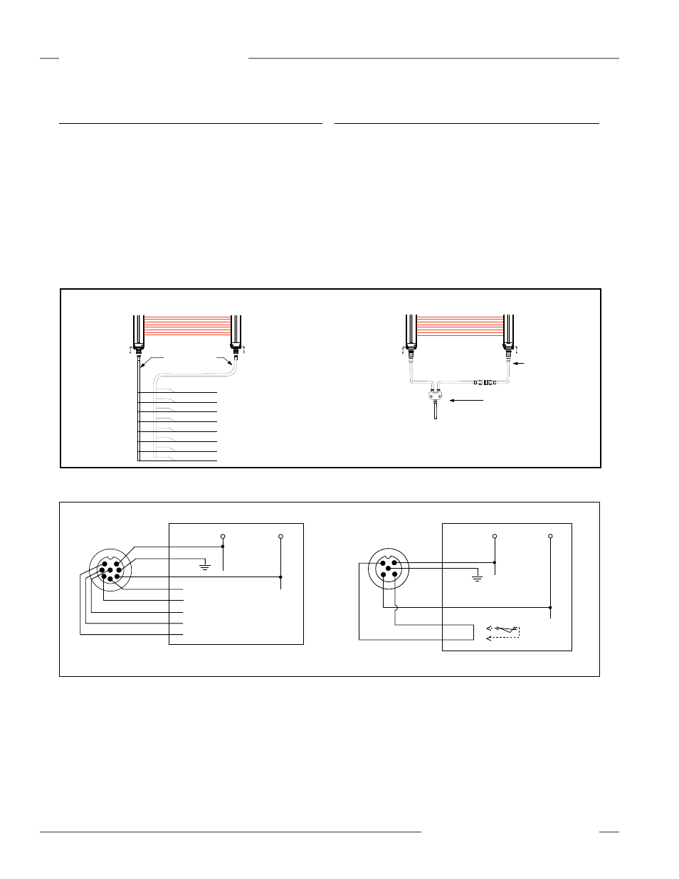
Figure 3-19. Emitters and receivers interchange easily when 8-pin connectors are used for both (optional hookup)
Figure 3-20. Emitter; generic hookup
3.6 Preparing for System Operation
After the initial trip test has been accomplished, the OSSD
safety outputs and EDM connections have been made to the
machine to be controlled, the EZ-SCREEN is ready for testing in
combination with the guarded machine.
The operation of the EZ-SCREEN with the guarded machine
must be verified before the combined EZ-SCREEN and machine
may be put into service. To do this, a Qualified Person must
perform the Commissioning Checkout Procedure described
in Section 6.2.
3.7 Sensor “Swapability” and the Optional Emitter Hookup
Figure 3-16 illustrates an optional hookup that provides sensor
interchangeability (or “swapability”) – the ability to install either
sensor at either QD connection. To hook up an 8-pin QD emitter,
use only three conductors (Brown = +24V dc, Blue = 0V dc,
Green/Yellow = GND). Connect the remaining wires in a parallel
connection (color-for-color) to the receiver cable.
The resulting installation provides the ability to swap the emitter
and receiver position, similar to a popular feature of Banner
MACHINE-GUARD
™
, MINI-SCREEN
®
and MICRO-SCREEN
®
safety light screens. This hookup option provides advantages
during installation, wiring, and troubleshooting.
Reset
Vi
Individual 8-wire Cordsets
8-wire Splitter Cordsets
Bn
Or
Or/Bk
Receiver
QDE-8..D Cables
OSSD2
Wh
0V dc
EDM1
EDM2 / Aux
+24 dc
OSSD1
Bu
Emitter
Bk
Ground
Emitter
CSB.. Splitter Cordset
DEE2R..
Gn/Ye
See above or
Section 2.2
for pinout
Receiver
Model CSB.. splitter cordsets and DEE2R.. double-ended cables allow easy
interconnection between an EZ-SCREEN receiver and emitter, providing a single
“homerun” cable for the optional “swapable” hookup (see Section 2.2 Cables).
Emitter (Standard)
Emitter (with Test)
or
0V dc
+24 dc
8-pin male
Euro-style
†
Bn (#1)
Or (#3)
Jumper
Wh (#4)
open to test
Gn/Ye (#7)
Bu (#6)
Vi (#8)
Bk (#5)
*NOTE: Pins 2, 3, 4, 5, and 8 are not connected, or are paralleled to
same color wire from the 8-pin receiver cable (see Section 3.7
and Figure 3-16).
n.c.*
n.c.*
n.c.*
n.c.*
n.c.*
Or/Bk (#2)
5-pin male
Euro-style
†
0V dc
+24 dc
Bn (#1)
Wh (#2)
Gn/Ye (#5)
Bu (#3)
Bk (#4)
†
See Table 2.2 for further cable information.