Overview, Installation and alignment, 7 use of corner mirrors – Banner EZ-SCREEN Safety Light Curtain Systems User Manual
Page 27: 6 adjacent reflective surfaces, Warning
P/N 133487
25
Banner Engineering Corp.
•
Minneapolis, U.S.A.
www.bannerengineering.com
•
Tel: 763.544.3164
Overview
25
Banner Engineering Corp.
•
Minneapolis, U.S.A.
www.bannerengineering.com
•
Tel: 763.544.3164
EZ-SCREEN
Instruction Manual
Installation and Alignment
3.1.7 Use of Corner Mirrors
EZ-SCREEN may be used with one or more corner mirrors
(see Section 2.4). The use of glass-surface corner mirrors
reduces the maximum specified emitter/receiver separation by
approximately 8 percent per mirror, as follows:
Figure 3-6. Adjacent reflective surfaces
3.1.6 Adjacent Reflective Surfaces
A reflective surface located adjacent to the defined area may
deflect one or more beams around an object in the defined area.
In the worst case, an “optical short circuit” may occur, allowing
an object to pass undetected through the defined area (see
Figure 3-6).
This reflective surface may result from shiny surfaces or glossy
paint on the machine, the workpiece, the work surface, the
floor or the walls. Beams deflected by reflective surfaces
are discovered by performing the trip test portion of the final
alignment procedure and the periodic checkout procedures
(Section 3.4.4).
To eliminate problem reflections:
• If possible, relocate the sensors to move the beams away
from the reflective surface(s), being careful to maintain
adequate separation distance (see Figure 3-6).
• Otherwise, if possible, paint, mask or roughen the shiny
surface to reduce its reflectivity.
•
Where these are not possible (as with a shiny workpiece),
mount the sensors in such a way that the receiver’s field of
view and/or the emitter’s spread of light are restricted.
•
Repeat the trip test to verify that these changes have
eliminated the problem reflection(s). If the workpiece is
especially reflective and comes close to the defined area,
perform the trip test with the workpiece in place.
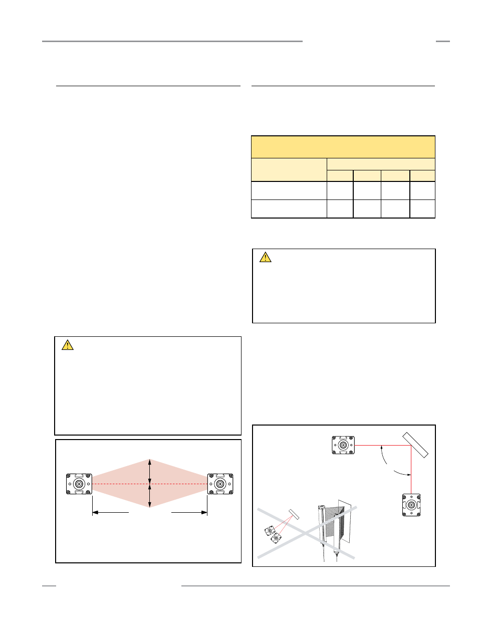
Mirrors are not allowed for applications that would allow
personnel undetected access into the safeguarded area.
If mirrors are used, the difference between the angle of
incidence from the emitter to the mirror and from the mirror to
the receiver must be between 45° and 120° (see Figure 3-7).
If placed at a sharper angle, as shown in the example, an
object in the light screen may deflect beam(s) to the receiver,
preventing the object from being detected (i.e., “false proxing”).
Angles greater than 120° result in difficult alignment and
possible optical short circuits.
See the specific mirror data sheet or the Banner Safety Catalog
for further information.
SSM and MSM Series Glass-Surface Mirrors –
Maximum Emitter and Receiver Separation
Sensor Models
Number of Corner Mirrors
1
2
3
4
14 mm Resolution Models
6 m (20') Range
5.5 m
(18')
5.1 m
(17')
4.7 m
(15.5')
4.3 m
(14')
30 mm Resolution Models
18 m (60') Range
16.6 m
(54.5')
15.3 m
(50')
14.1 m
(46.5')
13 m
(43')
Figure 3-7. Never use EZ-SCREEN sensors in a retroreflective mode.
WARNING . . .
Avoid Retroreflective
Installation
Do not install emitters and receivers in “retroreflective” mode,
with less than a 45° angle of incidence, as shown in Figure 3-7.
Sensing could be unreliable in this configuration; serious
bodily injury or death could result.
WARNING . . .
Avoid Installation Near
Reflective Surfaces
Avoid locating the defined area near a reflective surface; it could
reflect sensing beam(s) around an object or person within the
defined area, and prevent its detection by the EZ-SCREEN System.
Perform the trip test, as described in Section 3.4.4, to detect such
reflection(s) and the resultant optical short circuit.
Failure to prevent reflection problems will result in incomplete
guarding and could result in serious bodily injury or death.
Recommended sensor
configuration angle:
45° < A < 120°
Mirror
A
Receiver
Emitter
Mirror
Receiver
Emitter
Emitter
Receiver
Do not position reflective surfaces
within the shaded area
Operating Range
(R)
At installed operating range (R):
d=0.0437 × R (m or ft)
Operating range 0.1 to 3 m (4" to 10'): d = 0.13 m (5")
Operating range >3 m ( > 10’): d = 0.0437 × R (m or ft)
d
d