Overview, Troubleshooting and maintenance, 2 test mode (5-pin emitters only) – Banner EZ-SCREEN Safety Light Curtain Systems User Manual
Page 52: 2 emitter error codes
50
P/N 133487
Banner Engineering Corp.
•
Minneapolis, U.S.A.
www.bannerengineering.com
•
Tel: 763.544.3164
Overview
50
Banner Engineering Corp.
•
Minneapolis, U.S.A.
www.bannerengineering.com
•
Tel: 763.544.3164
EZ-SCREEN
Instruction Manual
Troubleshooting and Maintenance
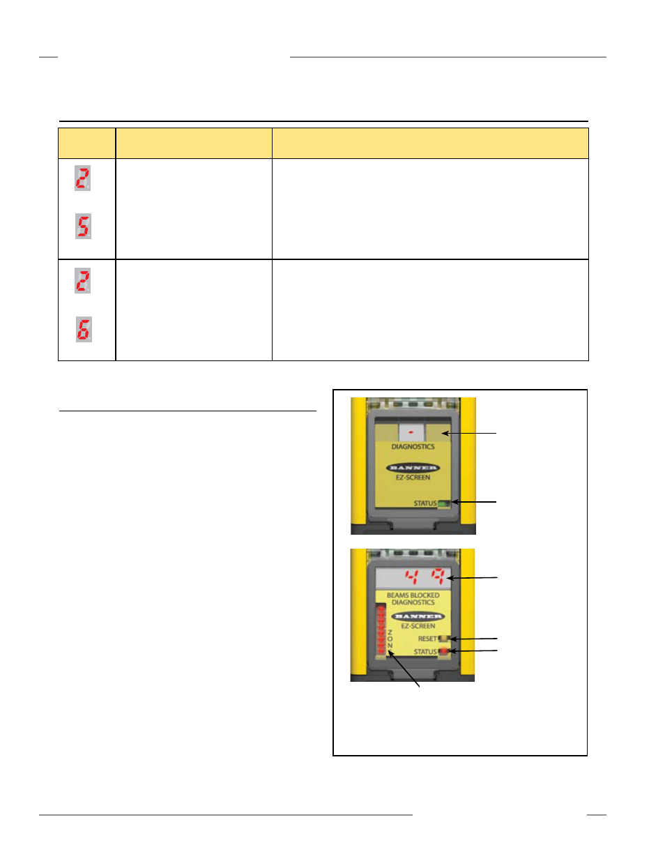
5.2 Test Mode (5-Pin Emitters only)
If System can not be aligned or it will not go to a Green/
Clear condition, the emitter’s TEST input may be open.
When this occurs, the receiver Reset indicator is Yellow, all
Zone indicators will be Red or Green, and the system Status
LED will be Red; the 3-digit display will show a numerical value
equal to one less than the total number of beams. For example,
if an array has 50 beams total, the display would show 49. The
emitter’s Status indicator will flash Green. See Section 4.4 and
Figure 5-1. (However, on a 10-beam system only, the Zone 1
indicator will be Green, and all others Red.)
Opening a switch or relay contacts connected to the TEST1 and
TEST2 connections of the emitter, or supplying a voltage of less
than 3V dc to TEST1 only, simulates a Blocked condition, for
testing purposes.
To verify proper operation, measure the voltage between TEST1
(pin 4, black) and dc COM (pin 3, blue) of the emitter:
•
If the voltage is 10 to 30V dc, the emitter should be in Run
mode and beam scanning should be occurring. If not, check
the +24V dc (pin 1, brown) to verify proper supply voltage.
If the supply voltage is not within the rated supply voltage
specifications, correct the supply voltage and recheck emitter
operation. If the supply voltage is correct, Test1 is 10 to 30V
dc and the emitter does not operate properly (RUN mode with
beam scanning). Replace emitter.
•
If the voltage is less than 3V dc, the emitter should be in Test
mode and no scanning should be occurring. If not in Test
mode, replace emitter.
Figure 5-1. TEST mode status indicators
5.1.2 Emitter Error Codes
Diagnostic
Display*
Error Description
Cause of Error and Appropriate Action
Emitter Error
This error can occur either due to
excessive electrical noise or due to an
internal failure.
•
Reset the emitter by cycling power to the emitter (see Section 4.3.2).
• If the error clears, perform a Daily Checkout procedure (Section 6.3) and if OK,
resume operation. If the System fails the Daily Checkout procedure, replace the
emitter.
• If the error continues, check the ground connection (see Section 2.3).
•
If the sensor has a good earth ground connection, check for electrical noise (see
Section 5.3).
• If the error continues, replace the emitter.
Excessive Noise Error
This error can occur due to excessive
electrical noise.
•
Reset the emitter by cycling power to the emitter (see Section 4.3.2).
•
If the error clears, perform a Daily Checkout procedure (Section 6.3) and if OK,
resume operation. If the System fails the Daily Checkout procedure, replace the
emitter.
• If the error continues, check the ground connection (see Section 2.3).
•
If the sensor has a good earth ground connection, check for electrical noise (see
Section 5.3).
• If the error continues, replace the emitter.
then
then
*Emitter has only 1-digit display. Two-digit codes are displayed sequentially.
* The 3-digit display will show a numerical value equal to one less than
the total number of beams. For example, if an array has 50 beams total,
the display would show 49.
Receiver
Emitter
All Red (except for 10-beam systems,
where Zone 1 indicator will be Green)
Dash
Flashing Green
Total number of beams
(less one)*
Yellow
Red