Overview, System operation, Inverted display – Banner EZ-SCREEN Safety Light Curtain Systems User Manual
Page 46
44
P/N 133487
Banner Engineering Corp.
•
Minneapolis, U.S.A.
www.bannerengineering.com
•
Tel: 763.544.3164
Overview
44
Banner Engineering Corp.
•
Minneapolis, U.S.A.
www.bannerengineering.com
•
Tel: 763.544.3164
EZ-SCREEN
Instruction Manual
System Operation
Figure 4-5. Receiver status indicator operation (Latch Output configured)
Operating
Mode
Required
Event
Reset
Indicator
Status
Indicator
Zone
Indicators*
Diagnostic Displays
OSSD
Outputs
Power-up
Apply power
OFF
Single-
Flash Red
All
Single-Flash
Red
Scan code flash
3x – alternates
OFF
Alignment Mode –
Beam 1 Blocked
Pass internal
tests
OFF
OFF
Zone 1 Red*,
Others OFF
OFF
Alignment Mode –
Beam 1 Clear
Align
Beam 1
ON
Red
Beam 1 Green,
others Red or
Green
Total number of blocked beams
OFF
Alignment Mode –
All Beams Clear
Align
all beams
Double-
Flash
Red
All ON Green
OFF
OFF
OFF
Run Mode –
Clear
Perform
reset
ON
ON or
Flashing
Green
†
All ON Green
OFF
OFF
ON
Latched – Blocked
Beam 1 Blocked
Block
Beam 1
ON
Red
Red or Green*
OFF
Latched – Blocked
Beam 1 Clear
Block 1 or
more beams
ON
Red
Red or Green*
Total number of blocked beams
OFF
Latched – Clear
Clear all
beams
Flashing
Red
All ON Green
OFF
OFF
OFF
Noise Detected –
Reset Interface
Flashing
Continues
previous
reading
Continues
previous
reading
Noise Detected –
EDM Interface
Continues
previous
reading
Continues
previous
reading
Flashing
Lockout
Internal/
external fault
OFF
Flashing
Red
OFF
Displays error code (see Section 5.1)
OFF
then
or
then
* NOTE: If beam 1 is blocked, Zone indicators 2-8 will be OFF, because beam 1 provides the synchronization signal for all the beams.
†
Flashing if Reduced Resolution is enabled.
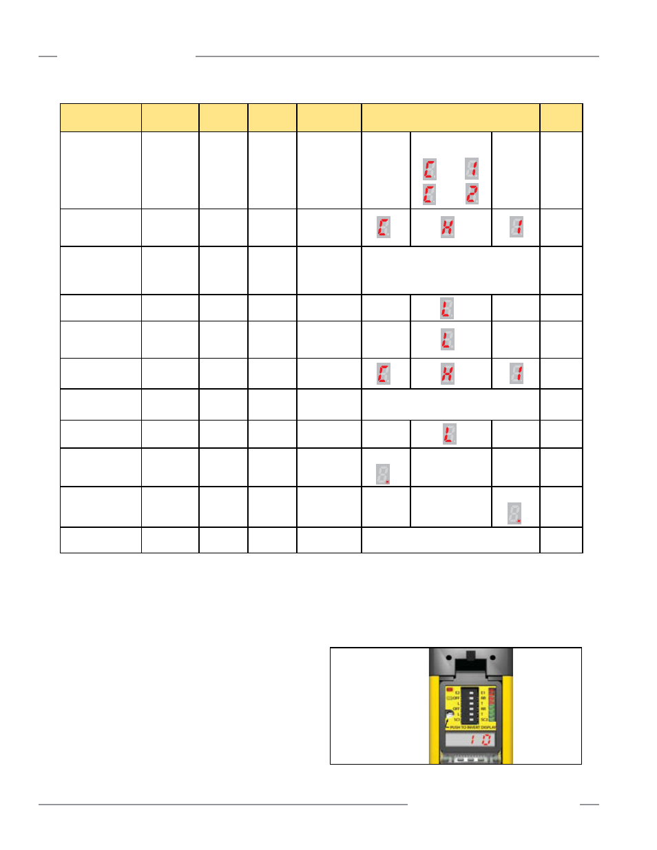
Figure 4-6. Inverted display showing the number 10 and the
inverted label
Inverted Display
For applications that require the emitter and receiver to be
inverted (with the status indicator ends at the “top”), the
7-segment displays on EZ-SCREEN emitters and receivers
can be inverted for easy reading. Press the Invert Display push
button, located next to the DIP switches, under the access cover
(Figure 4-6). A single momentary push is required; if pressed too
long (longer than 1/2 second), the display will not invert.
A spare access cover with inverted label and an inverted label
for the display are provided in the hardware packets for each
emitter and receiver (or see Section 2.5 Replacement Parts).
Remove the standard access cover by removing the screw-on
security plate and gently pulling the cover out. Place the inverted
label over the existing label on the display (adjacent to the DIP
switches) and snap the inverted-label access cover into place;
replace screw-on security plate if desired.