Overview, Installation and alignment, 4 optional remote test input – Banner EZ-SCREEN Safety Light Curtain Systems User Manual
Page 39: 5 auxiliary (aux) output
P/N 133487
37
Banner Engineering Corp.
•
Minneapolis, U.S.A.
www.bannerengineering.com
•
Tel: 763.544.3164
Overview
37
Banner Engineering Corp.
•
Minneapolis, U.S.A.
www.bannerengineering.com
•
Tel: 763.544.3164
EZ-SCREEN
Instruction Manual
Installation and Alignment
Refer to Figures 3-21 or 3-23 for 2-channel EDM hookup.
Connect the monitor contacts as shown between +24V dc and
EDM1 (pin 3) and between +24V dc and EDM2 (pin 2). Set the
configuration DIP switch to E2, per Section 4.2.
NOTE: For EZ-SCREEN receivers with a date code prior to
0834, the monitoring contacts must always close within
200 milliseconds of the corresponding OSSD state
change (turning OFF) or a lockout will occur.
No Monitoring: Use this configuration initially, in order to
perform the initial checkout; see Section 3.6. If the application
does not require the EDM function, it is the user’s responsibility
to ensure that this configuration does not create a hazardous
situation.
Refer to Figure 3-22 for “no monitoring” hookup. To configure
the EZ-SCREEN for no monitoring, connect or jumper EDM1
(pin 3) to EDM2 (pin 2) using the supplied wire-nut. Set the
configuration DIP switch to E2, per Section 4.2.
An alternate method to configure no monitoring is to set the
configuration DIP switch to E1 (1-channel monitoring), per
Section 4.2, and connect EDM1 (pin 3) to +24V dc. This method
allows the ability to use the auxiliary output (see Section 3.5.5)
in applications that do not require the EDM function.
3.5.4 Optional Remote Test Input
A pair of connections is provided on 5-pin emitters (Test1 and
Test2) for the connection of an external remote test switch
(typically a normally open contact held closed). Opening this
switch “turns OFF” the emitter, simulating an interruption of the
light beams; all OSSD outputs will turn OFF. See Sections 2.7.2,
3.3.1, and Figure 3-20.
3.5.5 Auxiliary (Aux) Output
On EZ-SCREEN receivers with date code 0834 or newer,
an auxiliary status output is available that provides a PNP
current-sourcing output (75 mA max.) that mirrors the state of
the OSSDs. The output is on pin 2 (orange/black wire) when
the EDM configuration DIP switch is set to E1 (1-channel
monitoring), per Section 4.2. See the 1-channel EDM circuit on
Figure 3-23 for hookup information.
To use the auxiliary output in an application configured for no
monitoring, set the configuration DIP switch to E1 (1-channel
monitoring) per Section 4.2., and connect EDM1 (pin 3) to
+24V dc (see Section 3.5.3).
There are no compatibility issues retrofitting receivers with
aux output into earlier installations, if precautions are taken to
prevent EDM2 (pin 2, orange/black wire) from shorting to ground
or another source of energy.
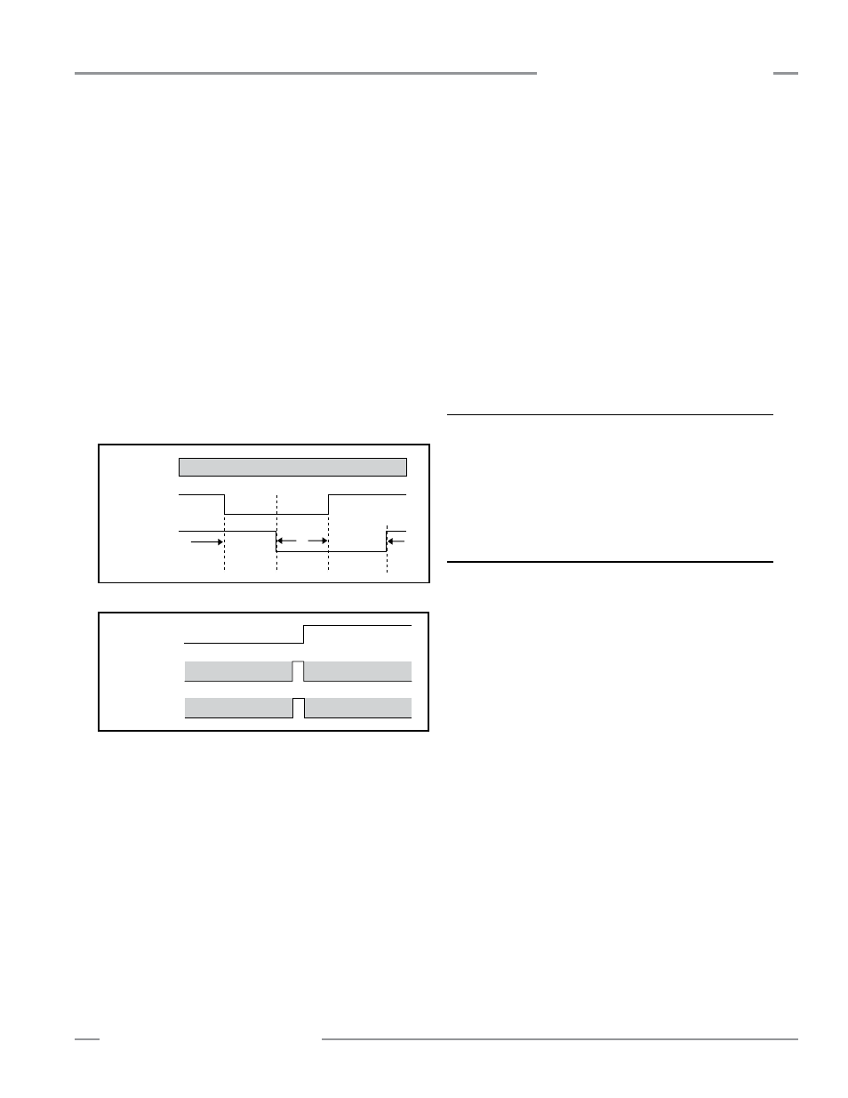
Safety Output
250 ms
Max.
250 ms
Max.
250 ms
Max.
250 ms
Max.
Don’t Care
Closed
Open
Closed
Open
EDM 1
EDM 2
Figure 3-17. Two-channel EDM, timing between channels
Figure 3-18. Two-channel EDM status, with respect to safety
output
Refer to Figure 3-23 for 1-channel EDM hookup. Connect the
monitor contacts between +24V dc and EDM1 (pin 3). Leave
EDM2 (pin 2) open (no connection). Set the configuration DIP
switch to E1, per Section 4.2.
NOTE: For EZ-SCREEN receivers with a date code prior to
0834, the monitoring contacts must open within 200
milliseconds of the OSSD outputs turning ON (a clear
condition) and must close within 200 milliseconds of the
OSSD outputs turning OFF (a blocked condition) or a
lockout will occur.
Two-Channel Monitoring: This is an independent connection
of closed monitor contacts that are forced-guided (mechanically
linked) from each device controlled by the EZ-SCREEN. The
monitor contacts must be closed before the EZ-SCREEN can be
reset and the OSSDs can turn ON. Regardless of the state of
the OSSDs, the monitor contacts may change state (either both
open, or both closed). If the monitor contacts remain in opposite
states for more than 250 milliseconds, a lockout will occur.
Safety Output
Closed
Open
Closed
Open
OFF
ON
EDM 1
EDM 2
Must Match EDM 1
Must Match EDM 1
Must Match EDM 2
Must Match EDM 2
Must Match EDM 1
Must Match EDM 1
Must Match EDM 2
Must Match EDM 2