Overview, System operation, 1 security protocol – Banner EZ-SCREEN Safety Light Curtain Systems User Manual
Page 43: 2 system configuration settings
P/N 133487
41
Banner Engineering Corp.
•
Minneapolis, U.S.A.
www.bannerengineering.com
•
Tel: 763.544.3164
Overview
41
Banner Engineering Corp.
•
Minneapolis, U.S.A.
www.bannerengineering.com
•
Tel: 763.544.3164
EZ-SCREEN
Instruction Manual
System Operation
4. System Operation
NOTE: The corresponding pairs of DIP switches must be set
identically for the System to operate.
Scan Code is used to allow operation of multiple pairs of
emitters and receivers in close proximity (see Sections 3.1.8 and
1.4.4). Scan Code may be set to 1 or 2, using the switch on the
configuration panel. The Scan Code setting for each emitter must
agree with its corresponding receiver. The Scan Code settings
may be changed while in RUN mode without causing a Lockout.
Trip or Latch Output operation is selected on two DIP switches
in the receiver configuration port; see Figure 4-1. Both switches
must be set to the same setting. If they have different settings,
an error code will be displayed.
If the switches are set for Trip Output (T), the System will auto-
reset. If the switches are set for Latch Output (L), the System will
require a manual reset.
External Device Monitoring (EDM)/Aux. Output: EDM mode is
selected via a 2-position DIP switch in the receiver configuration
port; see Figure 4-1. For 1-Channel Monitoring, set the EDM
DIP switch to the E1 position. For 2-Channel Monitoring or No
Monitoring, set the switch to the E2 position. See Section 3.5.3
for more information. When 1-Channel Monitoring is selected, an
aux. output is available; see Section 1.4.3.
Reduced Resolution: Two-beam Reduced Resolution can be
enabled by selecting “RR” on both DIP switches as labeled.
NOTE: Enabling Reduced Resolution will affect the Minimum
Separation Distance, see Section 3.1.1.
4.1 Security Protocol
Certain procedures for installing, maintaining and operating the
EZ-SCREEN system must be performed by either Designated
Persons or Qualified Persons.
A Designated Person is identified and designated in writing,
by the employer, as being appropriately trained and qualified to
perform system resets and the specified checkout procedures on
the EZ-SCREEN System. The Designated Person is empowered
to:
• Perform manual resets and hold possession of the reset key
(see Section 4.3), and
• Perform the Daily Checkout Procedure (see Section 6).
A Qualified Person, by possession of a recognized degree or
certificate of professional training, or by extensive knowledge,
training and experience, has successfully demonstrated the
ability to solve problems relating to the installation of the
EZ-SCREEN System and its integration with the guarded
machine. In addition to everything for which the Designated
Person is empowered, the Qualified Person is empowered to:
• Install the EZ-SCREEN System,
• Perform all checkout procedures (see Section 6),
• Make changes to the internal configuration settings, and
• Reset the System following a Lockout condition.
4.2 System Configuration Settings
If not previously configured, System settings are made on the
configuration panels located on each sensor, behind the access
cover. The access cover is opened by first removing the factory-
installed security plate with the security hex wrench provided. It
is recommended that the security plate be re-installed after any
configuration changes. See Figure 4-1.
Because it has redundant microprocessors, the receiver has
two DIP switch banks (bank A and bank B) which must be
set identically (see Section 4.2). Failure to do so will cause
a Lockout condition when power is applied. Power to the
EZ-SCREEN receiver should be OFF when changing DIP
switch settings or a Lockout will occur.
After configuration settings are verified/set, the access cover
must be fully closed (snap shut) to maintain IP ratings. Other
than Scan Code, all configuration settings should be
changed only when the System is OFF.
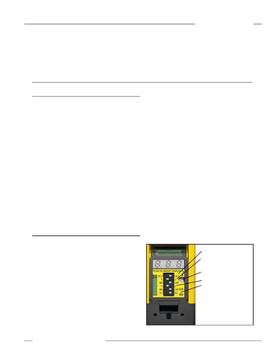
Figure 4-1. EZ-SCREEN configuration switches (receiver shown)
EDM (2-channel)* / Aux. Output
*(Default Setting)
See Figure 4-2 for access cover
opening instructions
Bank A
Trip or Latch Output (Trip Output)*
Reduced Resolution (OFF)*
Invert Display Push Button
Bank B (Identical to Bank A)
Scan Code 1 or 2 (SC1)*
NO TE: If the EDM wiring does not match
the switch position shown (E2), an
EDM error occurs and fixed blanking
or cascade configuration will not be
allowed.