Overview, Installation and alignment, 8 installation of multiple systems – Banner EZ-SCREEN Safety Light Curtain Systems User Manual
Page 28: Warning
26
P/N 133487
Banner Engineering Corp.
•
Minneapolis, U.S.A.
www.bannerengineering.com
•
Tel: 763.544.3164
Overview
26
Banner Engineering Corp.
•
Minneapolis, U.S.A.
www.bannerengineering.com
•
Tel: 763.544.3164
EZ-SCREEN
Instruction Manual
Installation and Alignment
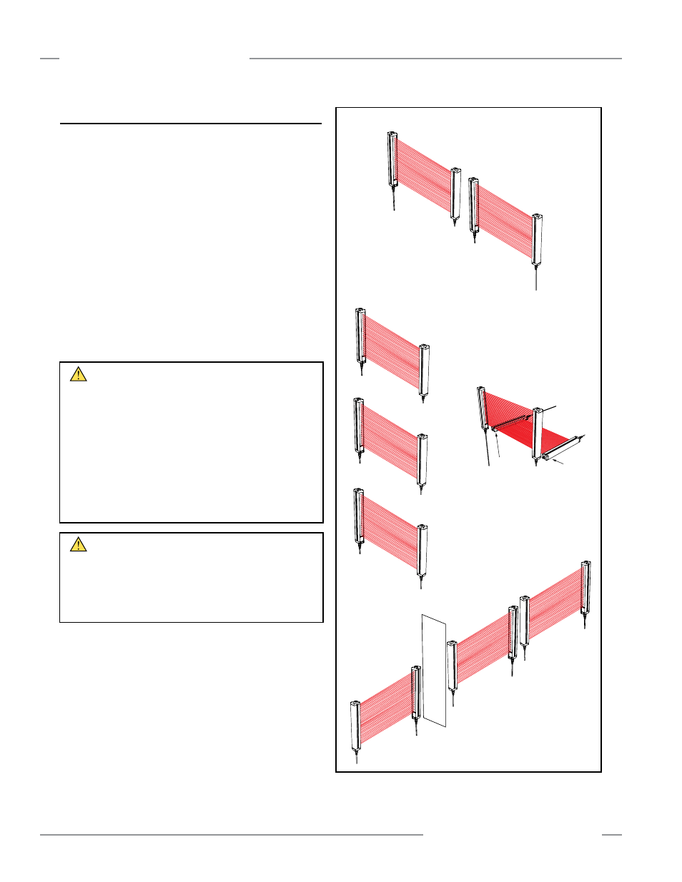
3.1.8 Installation of Multiple Systems
Whenever two or more EZ-SCREEN emitter and receiver pairs
are adjacent to one another, optical crosstalk may potentially
take place between systems. To minimize optical crosstalk,
alternate the positions of emitters and receivers, (see Figure
3-8a), or alternate Scan Codes.
When three or more sensor pairs are installed in the same plane
(as shown for two pairs in Figure 3-8), optical crosstalk may
occur between sensor pairs whose emitter and receiver lenses
are oriented in the same direction. In this situation, eliminate
optical crosstalk by mounting these sensor pairs exactly in line
with each other within one plane, or by adding a mechanical
barrier between the pairs.
To further aid in avoiding crosstalk, the sensors feature two
selectable Scan Codes. A receiver set to one Scan Code will not
“see” an emitter set to another code (see Section 4.2).
Receiver
Emitter
Receiver
Emitter
Scan Code 2
Receiver
Emitter
Scan Code 2
Scan Code 1
Figure 3-8. Installation of multiple pairs; alternate emitters and
receivers to avoid optical crosstalk.
WARNING . . .
Scan Code
In situations where multiple systems are mounted closely
together, or where a secondary emitter is in view (within ±5°),
within range of an adjacent receiver; the adjacent systems must be
configured for different Scan Codes (i.e., one system set for Scan
Code 1 and the other for Scan Code 2).
If not, a receiver may synchronize to the signal from the wrong
emitter, reducing the safety function of the light screen.
This situation will be discovered by performing the trip test
(see Section 3.4.3).
WARNING . . .
Multiple Pairs of Sensors
Do not connect multiple pairs of sensors to one Interface
Module (e.g., IM-T-9A/-11A) or otherwise parallel OSSD outputs.
Connection of multiple OSSD safety outputs to a single device
can result in serious bodily injury or death, and is prohibited.
a. Two pairs
in a horizontal plane
b. Two or three pairs stacked
(or alternate receiver/emitter positions)
Receiver 1
Emitter 1
Scan Code 1
Receiver 2
Emitter 2
Receiver 3
Scan Code 2
Scan Code 2
Emitter 3
Receiver
Emitter
Receiver
Emitter
Emitter
Horizontal
Receiver
Horizontal
Emitter
Receiver
Scan Code 1
Scan Code 2
c. Two pairs at right angles
d. Multiple pairs
in a horizontal plane
Opaque
Shield
Receiver 1
Emitter 1
Receiver 2
Emitter 2
Scan Code 2
Receiver 3
Emitter 3
Scan Code 1
Scan Code 2
Scan Code 1
Scan Code 1