Overview, Installation and alignment, 2 mechanical mounting procedure – Banner EZ-SCREEN Safety Light Curtain Systems User Manual
Page 30: 1 sensor mounting
28
P/N 133487
Banner Engineering Corp.
•
Minneapolis, U.S.A.
www.bannerengineering.com
•
Tel: 763.544.3164
Overview
28
Banner Engineering Corp.
•
Minneapolis, U.S.A.
www.bannerengineering.com
•
Tel: 763.544.3164
EZ-SCREEN
Instruction Manual
Installation and Alignment
3.2 Mechanical Mounting Procedure
Once the mechanical layout considerations of Section 3.1 are
addressed, mount the sensors and route the cables.
3.2.1 Sensor Mounting
Emitter/receiver pairs with 14 mm (0.55") resolution may be
spaced from 0.1 m to 6 m (4" to 20') apart. Emitter/receiver
pairs with 30 mm (1.18") resolution may be spaced from
0.1 m to 18 m (4" to 60') apart. The maximum distance between
an emitter and its receiver is reduced if corner mirrors are used
(see Section 3.1.7). The supplied brackets (when mounted to
the sensor end caps) allow ±30° rotation.
From a common point of reference (ensuring the minimum
separation distance calculated in Section 3.1.1), make
measurements to locate the emitter and receiver in the same
plane with their midpoints directly opposite each other.
Important: The connector ends of both sensors must point
in the same direction (see Figure 3-5 and warning, Section
3.1.3). Mount the emitter and receiver mounting brackets (see
below) using the supplied M6 bolts and Keps nuts, or user-
supplied hardware; see Figure 3-9.
Mount the emitter and receiver in their brackets; position their
windows directly facing each other. Measure from a reference
plane (e.g., a level building floor) to the same point(s) on the
emitter and receiver to verify their mechanical alignment. Use
a carpenter’s level, a plumb bob, or the optional LAT-1 Laser
Alignment Tool (see Section 2.5) or check the diagonal distances
between the sensors, to achieve mechanical alignment. Final
alignment procedures are explained in Section 3.4.
Center mounting brackets must be used with longer sensors,
whenever the sensors are subject to shock or vibration. In such
situations, the sensors are designed to be mounted with up
to 900 mm unsupported distance (between brackets). Sensors
1050 mm and longer are supplied with a center bracket to be
used as needed with the standard end-cap brackets (see Figure
3-9).
1. Attach the center bracket to the mounting surface when
mounting the end-cap brackets.
2. Attach the clamp to both slots of the housing, using the
included M5 screws and T-nuts.
3. After the sensor is mounted to the end-cap brackets, attach
the clamp to the center bracket using the supplied M5 screw.
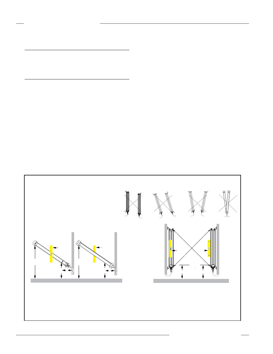
Figure 3-10. Sensor mounting, mechanical alignment
A
B
Verify that:
•
The emitter and receiver are directly opposite each other.
• Nothing is interrupting the defined area.
•
The defined area (marked on the sensors) is the same distance
from a common reference plane for each sensor.
•
The emitter and receiver are in the same plane and are
level/plumb and square to each other (vertical, horizontal,
or inclined at the same angle, and not tilted front-to-back or
side-to-side).
Angled or Horizontal Installations – verify that:
• Distance X at the emitter and receiver are equal.
• Distance Y at the emitter and receiver are equal.
• Distance Z at the emitter and receiver are equal from parallel
surfaces.
• Vertical face (i.e., the window) is level/plumb.
•
Defined area is square. Check diagonal measurements if possible; see
Vertical Installations, at right.
Vertical Installations – verify that:
• Distance X at the emitter and receiver are equal.
• Both sensors are level/plumb (check both the
side and face).
•
Defined area is square. Check diagonal measurements if
possible (Diagonal A = Diagonal B).
Receiver
Emitter
Level
Y
X
Z
Level Surface
Receiver
Emitter
Level
Y
X
Z
B
A
Level Surface
Level
X
Level
X