Best practices, Mounting, Standard installations – Rockwell Automation 1336T Wiring and Grounding Guide, (PWM) AC Drives User Manual
Page 57: Chapter 4, Chapter
Rockwell Automation Publication DRIVES-IN001M-EN-P - March 2014
57
Chapter
4
Best Practices
This chapter discusses various installation practices.
Mounting
Standard Installations
There are many criteria in determining the appropriate enclosure. Some of these
include:
•
Environment
•
EMC compatibility/compliance
•
Available space
•
Access/Wiring
•
Safety guidelines
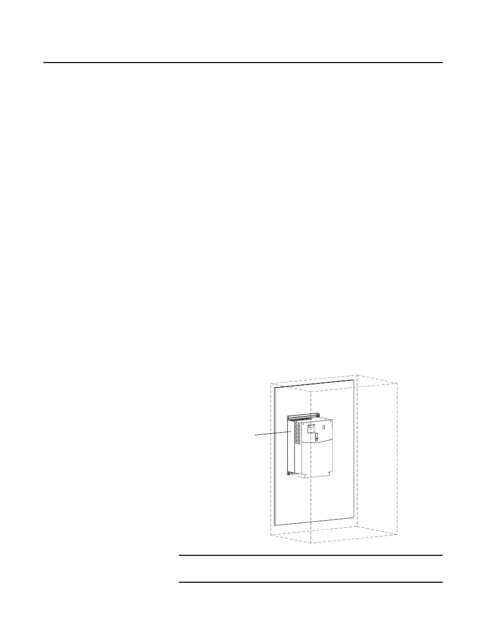
Grounding to the Component Mounting Panel
In the example below, the drive chassis ground plane is extended to the mounting
panel. The panel is made of zinc-plated steel that helps to create a proper bond
between chassis and panel.
Figure 20 - Drive Chassis Ground Plane Extended to the Panel
IMPORTANT
Where TE and PE terminals are provided, ground each separately to the nearest
point on the panel with flat braid.
Drive Ground Plane (chassis)
Bonded to Panel
- 1336E Wiring and Grounding Guide, (PWM) AC Drives 1336F Wiring and Grounding Guide, (PWM) AC Drives 1336S Wiring and Grounding Guide, (PWM) AC Drives 1336VT Wiring and Grounding Guide, (PWM) AC Drives 1336 Wiring and Grounding Guide, (PWM) AC Drives 1305 Wiring and Grounding Guide, (PWM) AC Drives 25B Wiring and Grounding Guide, (PWM) AC Drives 20N Wiring and Grounding Guide, (PWM) AC Drives 20M Wiring and Grounding Guide, (PWM) AC Drives 22C Wiring and Grounding Guide, (PWM) AC Drives 22B Wiring and Grounding Guide, (PWM) AC Drives 22A Wiring and Grounding Guide, (PWM) AC Drives 20D Wiring and Grounding Guide, (PWM) AC Drives 20C Wiring and Grounding Guide, (PWM) AC Drives 20B Wiring and Grounding Guide, (PWM) AC Drives 20A Wiring and Grounding Guide, (PWM) AC Drives 1336R Wiring and Grounding Guide, (PWM) AC Drives