Shielded cable – Rockwell Automation 1336T Wiring and Grounding Guide, (PWM) AC Drives User Manual
Page 16
16
Rockwell Automation Publication DRIVES-IN001M-EN-P - March 2014
Chapter 1 Wire/Cable Types
Chose the outer sheathing and other mechanical characteristics to suit the
installation environment. Consider the surrounding air temperature, chemical
environment, flexibility, and other factors in all installation types.
Shielded Cable
Shielded cable contains all of the general benefits of multi-conductor cable with
the added benefit of a copper-braided shield that can contain much of the noise
generated by a typical AC drive. Use shielded cable for installations with sensitive
equipment, such as weigh scales, capacitive proximity switches, and other devices
that can be affected by electrical noise in the distribution system. Applications
with large numbers of drives in a single location, imposed EMC regulations, or a
high degree of communication/networking, are also good candidates for shielded
cable.
Shielded cable can also help reduce shaft voltage and induced bearing currents for
some applications. In addition, the increased size of shielded cable can help
extend the distance that the motor can be from the drive without the addition of
motor protective devices, such as terminator networks. Refer to
for
information regarding reflected wave phenomena.
Consider all of the general specifications dictated by the environment of the
installation, including temperature, flexibility, moisture characteristics, and
chemical resistance. In addition, include a braided shield specified by the cable
manufacturer as having coverage of at least 75%. An additional foil shield can
greatly improve noise containment.
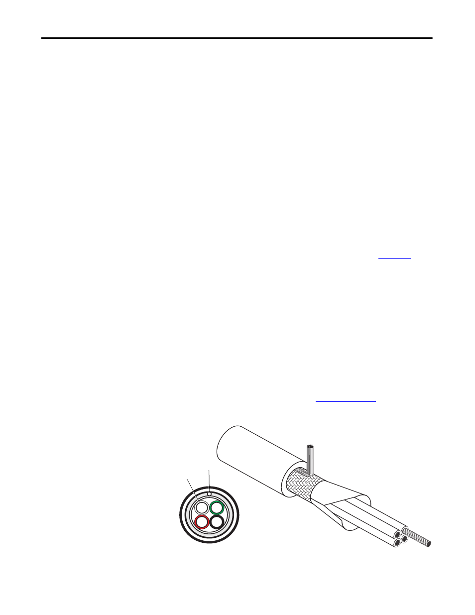
Type 1 Installation
An acceptable shielded cable for Type 1 installations has four XLPE insulated
conductors with a 100% coverage foil and an 85% coverage copper braided shield
(with drain wire) surrounded by a PVC jacket. For detailed specifications and
information on Type 1 installations, refer to
.
Figure 7 - Type 1 Installation — Shielded Cable with Four Conductors
B
R
G
W
Shield
Drain Wire
- 1336E Wiring and Grounding Guide, (PWM) AC Drives 1336F Wiring and Grounding Guide, (PWM) AC Drives 1336S Wiring and Grounding Guide, (PWM) AC Drives 1336VT Wiring and Grounding Guide, (PWM) AC Drives 1336 Wiring and Grounding Guide, (PWM) AC Drives 1305 Wiring and Grounding Guide, (PWM) AC Drives 25B Wiring and Grounding Guide, (PWM) AC Drives 20N Wiring and Grounding Guide, (PWM) AC Drives 20M Wiring and Grounding Guide, (PWM) AC Drives 22C Wiring and Grounding Guide, (PWM) AC Drives 22B Wiring and Grounding Guide, (PWM) AC Drives 22A Wiring and Grounding Guide, (PWM) AC Drives 20D Wiring and Grounding Guide, (PWM) AC Drives 20C Wiring and Grounding Guide, (PWM) AC Drives 20B Wiring and Grounding Guide, (PWM) AC Drives 20A Wiring and Grounding Guide, (PWM) AC Drives 1336R Wiring and Grounding Guide, (PWM) AC Drives