Braking chopper – Rockwell Automation 1336T Wiring and Grounding Guide, (PWM) AC Drives User Manual
Page 48
48
Rockwell Automation Publication DRIVES-IN001M-EN-P - March 2014
Chapter 2 Power Distribution
Braking Chopper
Connect the brake unit closest to the largest drive. If all of the drives are the same
rating, then connect the brake unit closest to the drive that regenerates the most.
In general, mount brake units within 3 m (9.8 ft) of the drive. Resistors for use
with chopper modules must be within 30 m (98.4 ft) of the chopper module.
Refer to the respective braking product documentation for details.
An RC snubber circuit is required when you use Allen-Bradley catalog number
1336-WA, 1336-WB, or 1336-WC brake choppers in the configurations listed
below:
•
A non-regenerative bus supply configuration that uses a PowerFlex diode
bus supply.
•
A shared AC/DC bus configuration containing a PowerFlex 700/700S
Frame 0…4 drive, or PowerFlex 40P drive.
•
A shared DC bus (piggy back) configuration when the main drive is a
PowerFlex 700/700S Frame 0…4, or PowerFlex 40P drive.
The RC snubber circuit is required to prevent the DC bus voltage from
exceeding the 1200V maximum brake chopper IGBT voltage. The 1336 brake
chopper power-up delay time is 80 ms. During this time, the IGBT does not turn
on. The RC snubber circuit must always be connected to the DC bus (found
close to the braking chopper) to absorb the power-on voltage overshoot (see
The specifications for the RC snubber are described here:
•
R = 10
Ω, 100 W, low inductance (less than 50 μH)
•
C = 20 μF, 2000V
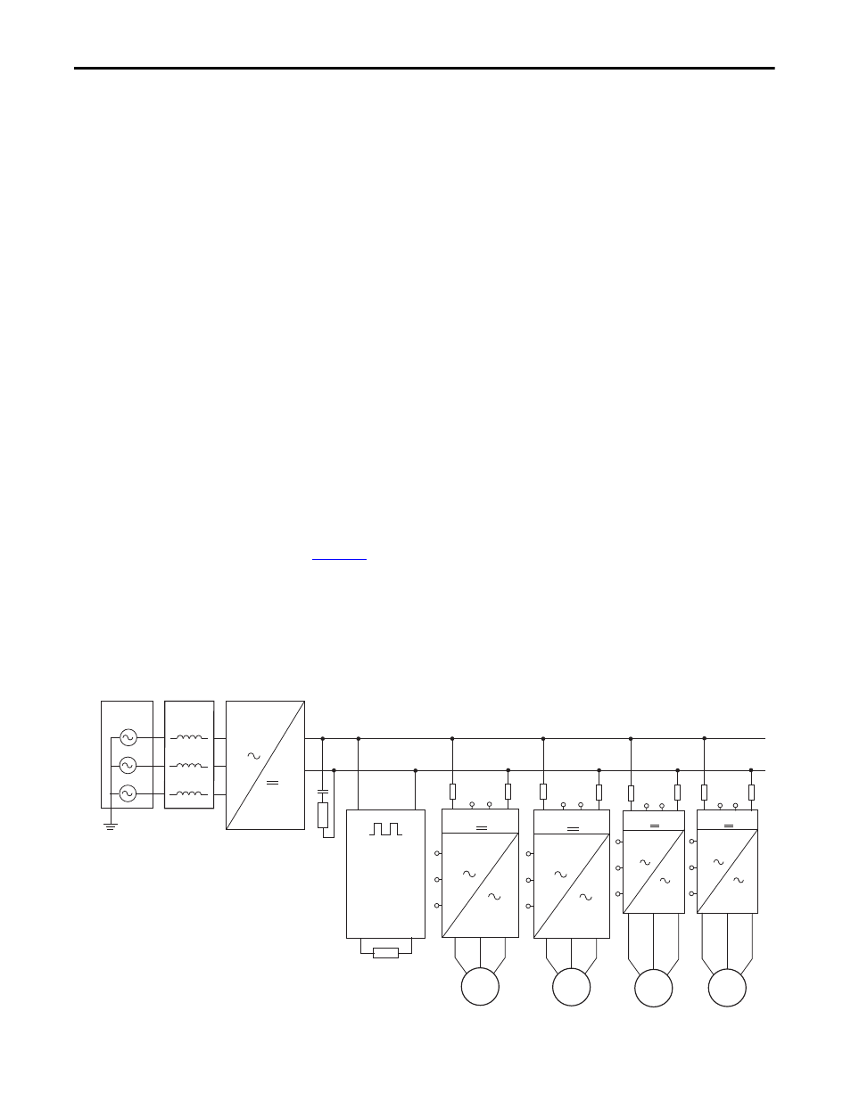
Figure 14 - Configuration Example of Diode Bus Supply with PowerFlex 700 Frame 0…4,
PowerFlex 40P, 1336-W Braking Chopper and RC Snubber Circuit.
L1
L2
L3
DC+
DC+
DC+
DC-
DC-
DC-
BR1 BR2
BR
M1
L1
L1
L2
L2
L3
L3
DC+
DC-
BR1 BR2
M2
BR1
BR2
PowerFlex 700
PowerFlex
PowerFlex 700
L1
L2
L3
DC+
DC-
BR+ BR-
M3
PowerFlex 40P
L1
L2
L3
DC+
DC-
BR+ BR-
M4
PowerFlex 40P
3-phase
Source
3-phase
Reactor
Diode Bus
Supply
Braking Unit
1336-W*
Frame 0…4
Frame 0…4
- 1336E Wiring and Grounding Guide, (PWM) AC Drives 1336F Wiring and Grounding Guide, (PWM) AC Drives 1336S Wiring and Grounding Guide, (PWM) AC Drives 1336VT Wiring and Grounding Guide, (PWM) AC Drives 1336 Wiring and Grounding Guide, (PWM) AC Drives 1305 Wiring and Grounding Guide, (PWM) AC Drives 25B Wiring and Grounding Guide, (PWM) AC Drives 20N Wiring and Grounding Guide, (PWM) AC Drives 20M Wiring and Grounding Guide, (PWM) AC Drives 22C Wiring and Grounding Guide, (PWM) AC Drives 22B Wiring and Grounding Guide, (PWM) AC Drives 22A Wiring and Grounding Guide, (PWM) AC Drives 20D Wiring and Grounding Guide, (PWM) AC Drives 20C Wiring and Grounding Guide, (PWM) AC Drives 20B Wiring and Grounding Guide, (PWM) AC Drives 20A Wiring and Grounding Guide, (PWM) AC Drives 1336R Wiring and Grounding Guide, (PWM) AC Drives