Cable shields, Isolated inputs, Cable shields isolated inputs – Rockwell Automation 1336T Wiring and Grounding Guide, (PWM) AC Drives User Manual
Page 55
Rockwell Automation Publication DRIVES-IN001M-EN-P - March 2014
55
Grounding Chapter 3
Cable Shields
Motor and Input Cables
Shields of motor and input cables must be bonded at both ends to provide a
continuous path for common mode noise current.
Control and Signal Cables
Connect the shields of control cables only at one end. Cut back and insulate the
other end. Follow these guidelines for connecting shields:
•
The shield for a cable from one cabinet to another must be connected at
the cabinet that contains the signal source.
•
The shield for a cable from a cabinet to an external device must be
connected at the cabinet end, unless specified by the manufacturer of the
external device.
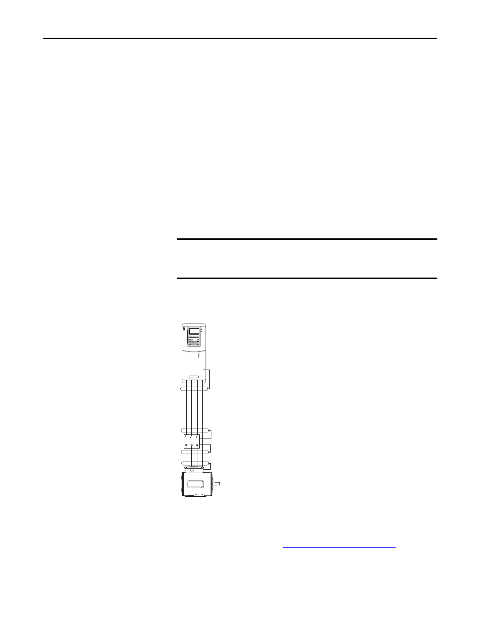
Shield Splicing
Figure 19 - Spliced Cable That Uses a Shieldhead Connector
If the shielded cable needs to be stripped, strip it back as little
as possible so the continuity of the shield is not interrupted.
Avoid splicing motor power cables whenever possible. Ideally,
run the motor cables continuously between the drive and
motor terminals. The most common reason for interrupted
cable/shield is to install a disconnect switch at the motor. In
these cases, the preferred method of splicing is to use fully
shielded bulkhead connectors.
Single Point – Connect a single safety ground point or ground
bus bar directly to the building steel for cabinet installations.
Ground all circuits, including the AC input ground
conductor, independently and directly to this point/bar.
Isolated Inputs
If the analog inputs of the drive are from isolated devices and
the output signal is not referenced to the ground, the inputs of the drive do not
need to be isolated. An isolated input is recommended to reduce the possibility of
induced noise if the signal from the transducer is referenced to ground and the
ground potentials are varied (see
Noise Related Grounds on page 51
). An
external isolator can be installed if the drive does not provide input isolation.
IMPORTANT
Never connect a shield to the common side of a logic circuit (doing so
introduces noise into the logic circuit).
Connect the shield directly to a chassis ground.
PE
- 1336E Wiring and Grounding Guide, (PWM) AC Drives 1336F Wiring and Grounding Guide, (PWM) AC Drives 1336S Wiring and Grounding Guide, (PWM) AC Drives 1336VT Wiring and Grounding Guide, (PWM) AC Drives 1336 Wiring and Grounding Guide, (PWM) AC Drives 1305 Wiring and Grounding Guide, (PWM) AC Drives 25B Wiring and Grounding Guide, (PWM) AC Drives 20N Wiring and Grounding Guide, (PWM) AC Drives 20M Wiring and Grounding Guide, (PWM) AC Drives 22C Wiring and Grounding Guide, (PWM) AC Drives 22B Wiring and Grounding Guide, (PWM) AC Drives 22A Wiring and Grounding Guide, (PWM) AC Drives 20D Wiring and Grounding Guide, (PWM) AC Drives 20C Wiring and Grounding Guide, (PWM) AC Drives 20B Wiring and Grounding Guide, (PWM) AC Drives 20A Wiring and Grounding Guide, (PWM) AC Drives 1336R Wiring and Grounding Guide, (PWM) AC Drives