Create a function block program, Create a function block program -13 – Rockwell Automation 1753-PCS-PAR Using RSLogix Guard PLUS! with GuardPLC Controllers User Manual
Page 53
Publication 1753-PM001A-EN-P - November 2005
Create a GuardPLC Project 3-13
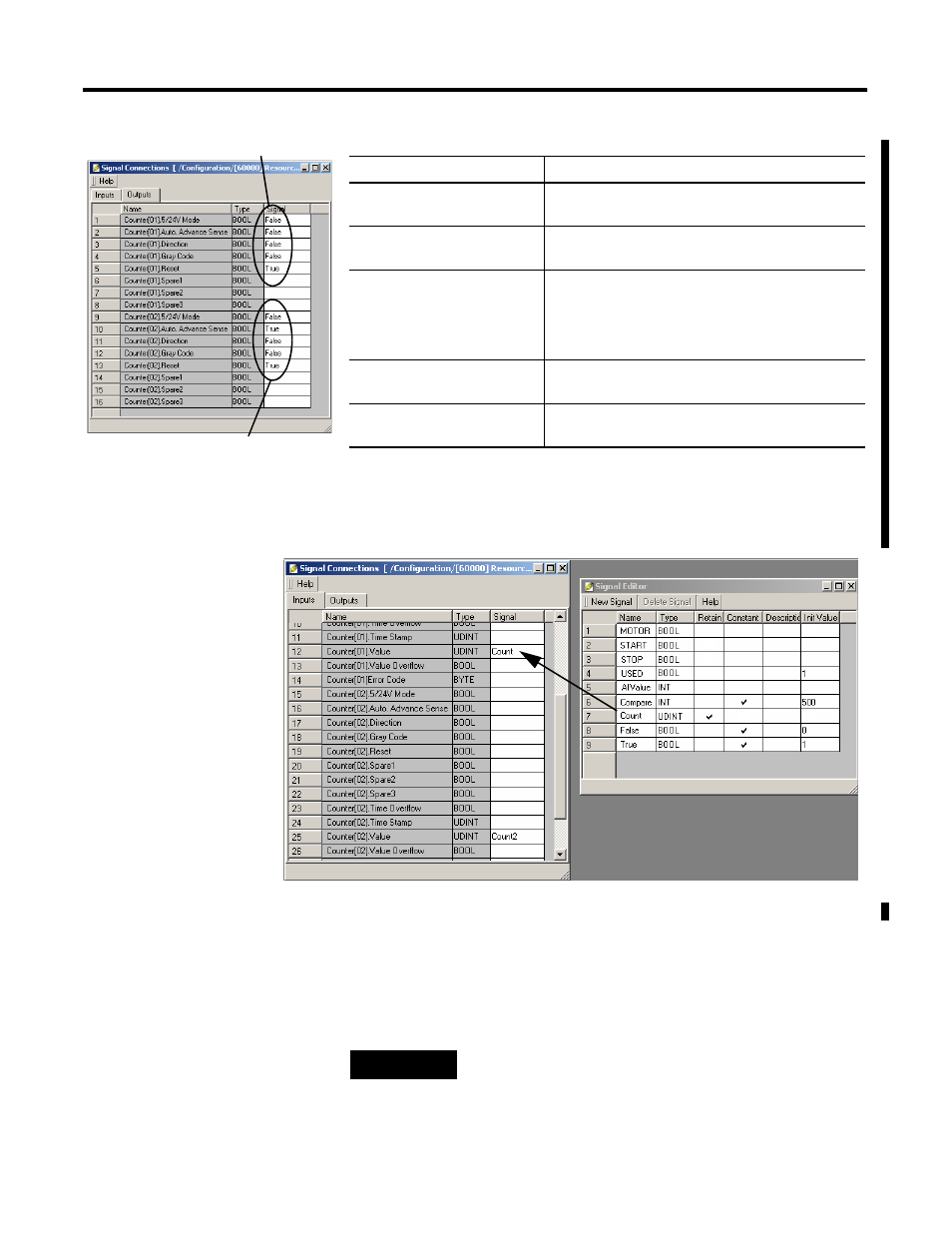
4. Select the Input tab on the Connect Signals dialog.
5. Connect the Count signal you created to the Counter Value
input.
These signals can now be used in your application program logic.
Create a Function Block
Program
The following example creates code to start and stop a motor using
the two input signals we created earlier.
Counter[xx] Output Variable
Description
5/24V Mode
True (1) = 24V
False (0) = 5V
Auto Advance Sense
True (1) = Count Up or Down Based on Direction
False (0) = Count Up Regardless of Direction
Direction
If Auto Advance Sense is False (0), then count in the
indicated Direction:
• True (1) = Down
• False (0) = Up
Gray Code
True (1) = Use Gray Code Mode
False (0) = Use Pulse Mode
Reset
True (1) = No Counter Reset
False (0) = Reset Counter
Count Up regardless of Direction
Count Up based on Direction
TIP
For more information on Function Block
programming, consult the online Help and
Chapter 8, Create User-Defined Function Blocks.