Rockwell Automation 1753-PCS-PAR Using RSLogix Guard PLUS! with GuardPLC Controllers User Manual
Page 48
Publication 1753-PM001A-EN-P - November 2005
3-8 Create a GuardPLC Project
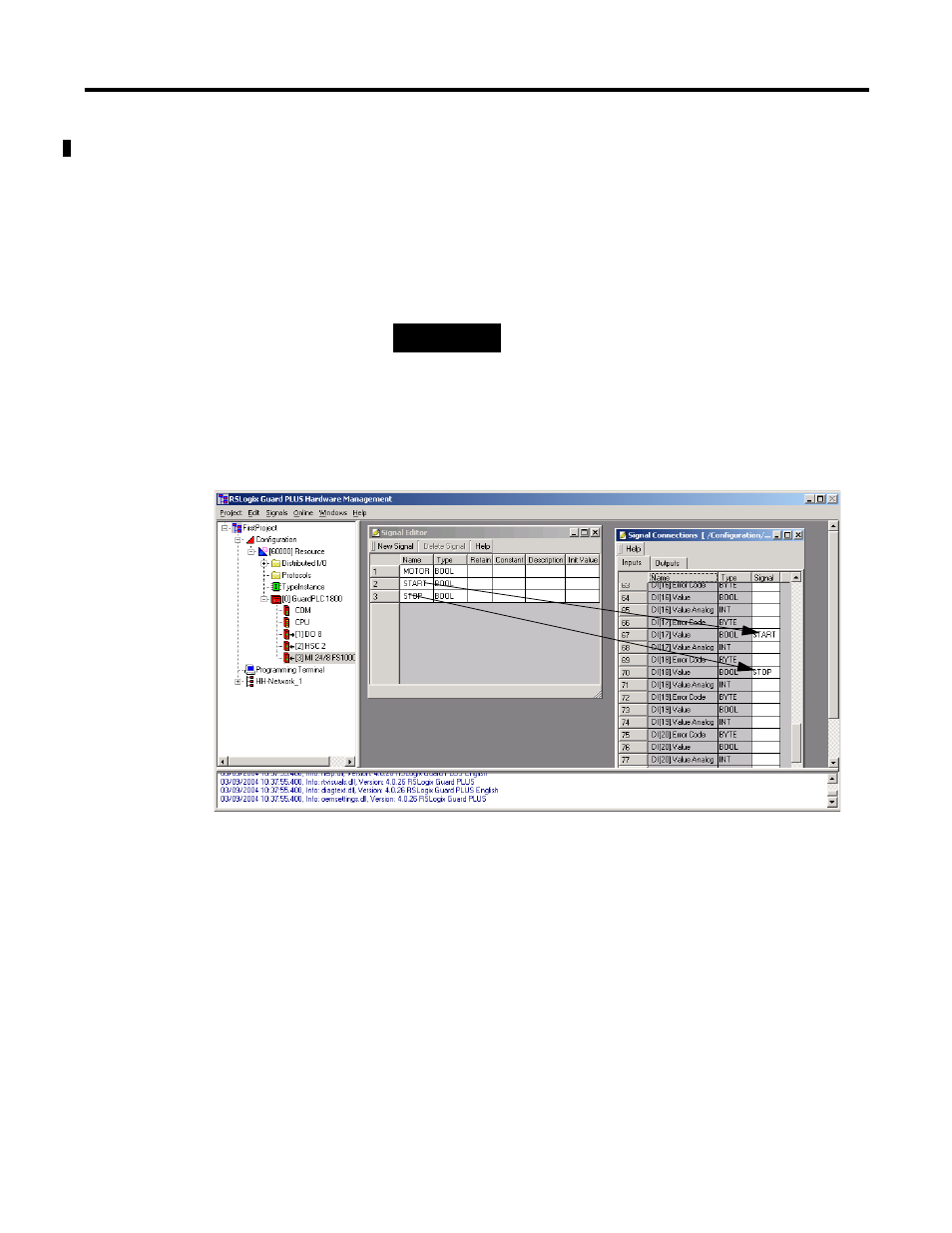
3. Connect the START and STOP signals to inputs by dragging
START and STOP from the Name field in the Signal Editor to the
Signal field in the Signal Connections window.
a. Make sure the cursor is not active in any field in either the
Signal Editor or the Signal Connections dialog.
b. Left-click and hold on the Name field. Drag the signal to the
Signal field in the Signal Connections dialog.
c. Release when over the proper field.
When both signals have been connected, the screens should
appear as follows:
4. If your controller is a GuardPLC 1800, an additional step is
required. The digital inputs on a GuardPLC 1800 controller are
actually analog circuits with a resolution of one (1) bit. Any
voltage greater than 13V dc will be a 1. Any voltage less than
7V dc will be a 0. Since GuardPLC analog circuits require the
user to specify which channels are being used, this is also
required for the 24 digital inputs on the GuardPLC 1800
controller.
a. Add a new signal, called USED, to the Signal Editor.
b. Give this signal an initial value of 1. You will never change
this value in your program, so USED will always be 1.
c. Choose the Outputs tab of MI 24/8 FS1000.
TIP
Signals can only be dragged and dropped onto
Signal fields of the same data type. Dropping a
BOOL signal onto a BYTE field is not
permitted.