Connect digital input signals -7, Connect digital input signals – Rockwell Automation 1753-PCS-PAR Using RSLogix Guard PLUS! with GuardPLC Controllers User Manual
Page 47
Publication 1753-PM001A-EN-P - November 2005
Create a GuardPLC Project 3-7
Connect Digital Input Signals
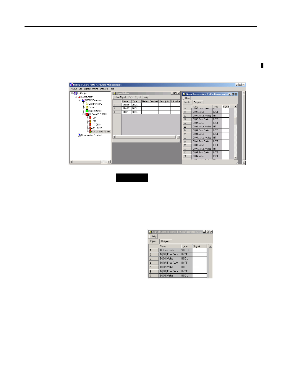
1. Right-click on the controller’s inputs (DI 20 for 1600 or MI 24/8
FS1000 for 1800) or on a Distributed I/O module and choose
Connect Signals.
2. Verify that the Inputs tab is selected on the Signal Connections
dialog.
Two signals exist for each input: Value and Error Code. The
GuardPLC 1800 controller adds another signal called Value
Analog.
Error Code is a status signal that can be used for point-level
diagnostics. The Value contains the actual field state of the input:
ON (1) or OFF (0).
TIP
Set up your screen so that you can easily drag
signals from the Signal Editor window to the
Signal Connections window. Both the Name
fields in the Signal Editor and the Signal fields
in the Signal Connections window must be
visible, as shown above.