Overview of the communication process, Important – Rockwell Automation 1738-ADNX ArmorPoint I/O DeviceNet Adapters User Manual
Page 35
Publication 1738-UM001A-EN-P - February 2005
What Is the ArmorPoint DeviceNet Adapter? 2-19
Overview of the Communication Process
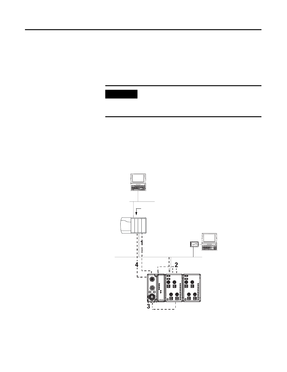
In a typical configuration, the adapter acts as an interface between a
DeviceNet scanner (e.g., 1756-DNB) and ArmorPoint I/O modules.
The following example graphic shows information transferred from a
1756-DNB to ArmorPoint I/O modules.
Four data transfers are shown in the diagram, including:
1. Scanner to adapter
2. Adapter to I/O modules
3. I/O modules to adapter
4. Adapter to scanner
Because the adapter simultaneously resides on the DeviceNet network
and on PointBus, it serves as a slave to the processor (i.e., steps 1 and
4) and a master to the I/O modules (i.e., steps 2 and 3).
IMPORTANT
Although information is exchanged between the
Logix5555 and 1756-DNB, this diagram (nor this
chapter) is not designed to explain such an
exchange.
0
0
2
1
2
3
4
6
1
3
4
5
6
7
5
7
MOD
NET
1738-OB8EM12
24V dc Out
1738-ADN12
Adapter
Status
DeviceNet
Status
PointBus
Status
System
Power
Adapter
Power
DeviceNet Out
DeviceNet In
PWR
x10
x1
6
0
8
2
4
6
0
8
2
4
0
0
2
1
2
3
4
6
1
3
4
5
6
7
5
7
MOD
NET
1738-IB8M12
24V dc In
computer with PLC
programming software
ControlNet network
Logix5555 controller
1784-PCD
PCMCIA card
1738-ADN adapter
DeviceNet network
computer with
RSNetWorx for
DeviceNet software
ArmorPoint I/O modules
42409
The computers and PCMCIA card
shown in the diagram are required
to configure the processor,
adapter, and I/O modules.
Although the PCMCIA card is used
in this example, you can use other
communications cards, such as
PCID and KFD cards.
Key Points About Scanner to Adapter Transfer (Step 1)
1. Scanner initiates transfer
2. Scanner uses DeviceNet I/O messaging to write data to adapter.
Data may contain:
• device output data
• configuration data
Key Points About Adapter to Output Module Transfer (Step 2)
1. Adapter initiates transfer
2. Adapter produces data for I/O module to consume.
Data may contain:
• device output data
• configuration data
Key Points About Input Module to Adapter Transfer (Step 3)
Adapter consumes data I/O module has produced.
Data may contain:
• device input data
• status data
Key Points About Adapter to Scanner Transfer (Step 4)
SDN consumes I/O data produced by adapter.
Data may contain:
• device input data
• status data
The Logix5555 controller sits in the backplane.
The 1756-DNB contained in the controller
communicates with the ArmorPoint adapter.