Start-up, Table 4 – Rockwell Automation MV SMC Flex Motor Controller (for Series K or later) User Manual
Page 79
Rockwell Automation Publication 1560E-UM051F-EN-P - June 2013
69
Commissioning Procedure
Chapter 3
Software will be used to scale the output to show the correct value on the SMC
Flex front panel display. (See Parameter #106 –
MV Ratio)
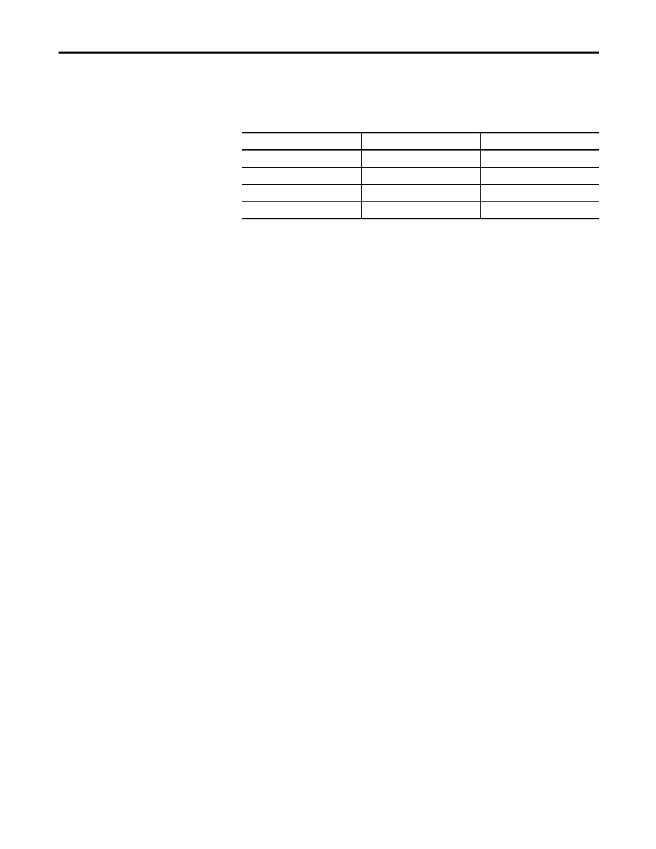
Table 4 - Input Voltage Ranges
The MV ratios shown above are nominal values and may be fine tuned to achieve
better accuracy on the display of the SMC Flex control module. While running
the motor in bypass mode, compare the voltage displayed on the control module
to a known accurate meter connected to the same source voltage as the motor the
MV SMC Flex is controlling. Parameter 106,
MV Ratio, may be changed up or
down to match the Flex display to the external meter. A small change in ratio can
make a large change in the display, so 5 units at a time is recommended.
Increasing the ratio will decrease the displayed voltage, and visa versa.
Start-Up
1.
Remove any temporary jumpers or grounding devices used during
commissioning.
2.
Check that all tools are removed from the equipment. Any tools or
hardware used or dropped during installation and commissioning must be
retrieved and accounted for.
3.
Check that all barriers or covers removed during installation or
commissioning have been securely mounted.
4.
Close and secure all doors, and verify function of all interlocks that
prevent access to medium voltage compartments when the unit is
energized.
5.
The controller is ready to power the motor.
Module Rated Voltage
Voltage Range
MV Ratio
1500
800-1500
1200
2500
1501-2500
580
4800
2501-4800
324
7200
4801-7200
195