General plenum layout for arcshield line-up – Rockwell Automation MV SMC Flex Motor Controller (for Series K or later) User Manual
Page 197
Rockwell Automation Publication 1560E-UM051F-EN-P - June 2013
187
ArcShield Plenum Installation Instructions
Appendix E
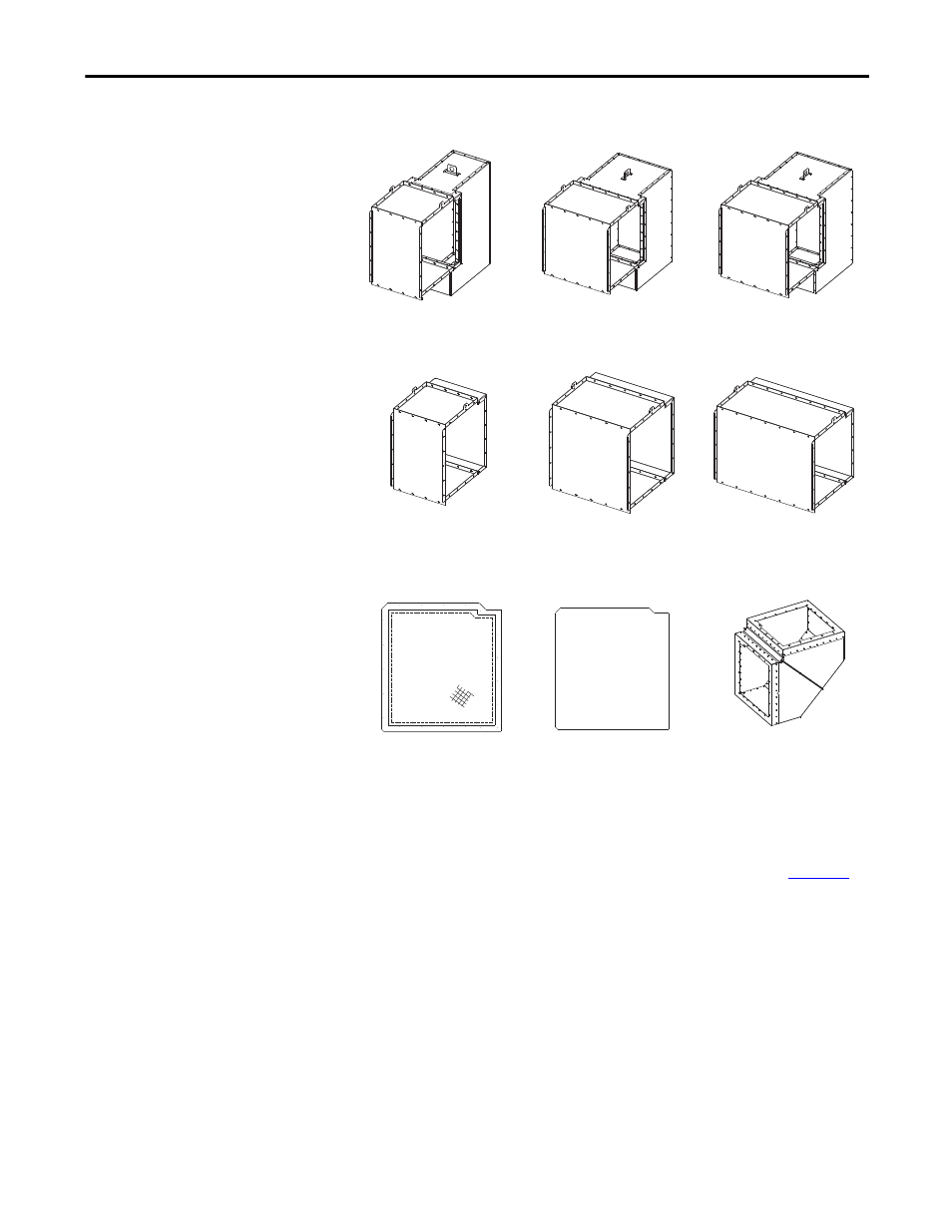
Figure 85 - Various Plenum Components Available
General Plenum Layout for
ArcShield Line-up
An example of a general Plenum assembly configuration is shown in
Figure 86
.
Plenums of varying widths are mounted directly over the MV enclosures of the
corresponding width. A 0.9 m (36 inch) Exhaust extension assembly is shown
mounted on the extreme right side Plenum of the equipment “Line-up” (can
alternatively exhaust to the left. Engineered systems can be made site specific).
18" wide Plenum
Fastened directly over the 0.5 m (18 inch)
wide cabinet
26" wide Plenum
Fastened directly over the 0.7 m (26 inch)
wide cabinet
36" wide Plenum
Fastened directly over the 0.9 m (36 inch)
wide cabinet
18" long Extension
Connected to the last Plenum on the
exhaust end of the “line-up”
26" long Extension
Connected to the last Plenum on the
exhaust end of the “line-up”
36" long Extension
Connected to the last Plenum on the
exhaust end of the “line-up”
Screen Cover Plate
Fastened at the opening of the last
component on the exhaust end
End Cover Plate
Fastened at the opening of the last
Plenum in the “line-up” opposite the
exhaust end to seal Plenum end
90° Elbow Section
Connected at the exhaust end of the
Plenum (or Extension)