Bornier de commande, Français-11, Schéma de principe du câblage de commande – Rockwell Automation 22D PowerFlex 40P Quick Start - FRN 1.xx - 3.xx User Manual
Page 55: Enbl
Français-11
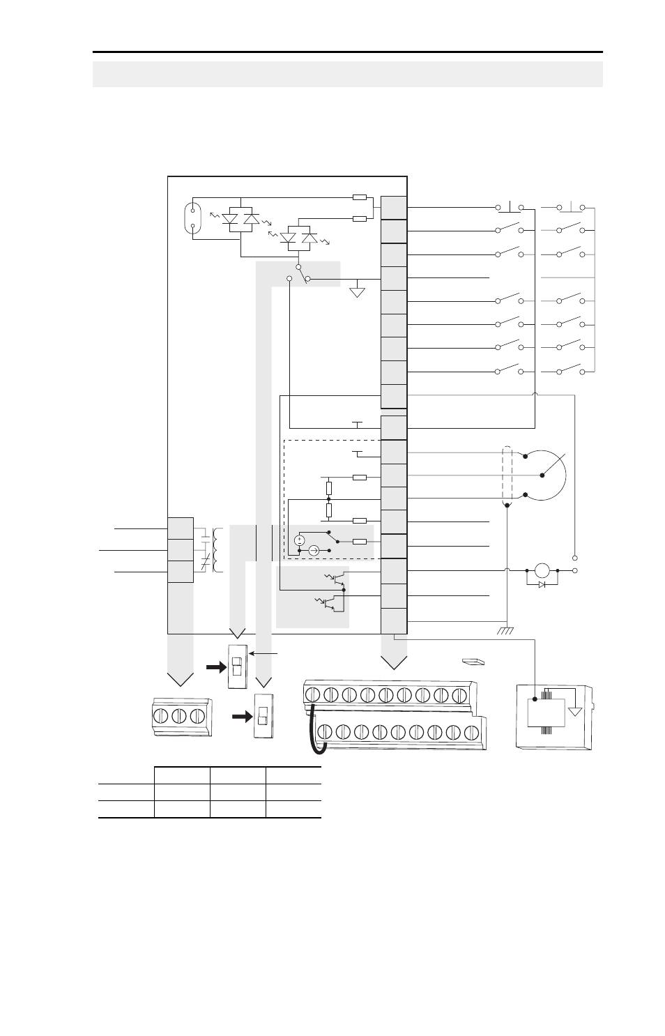
Schéma de principe du câblage de commande
Voir les remarques relatives au schéma de principe du câblage de
commande à la page suivante.
Bornier de commande
04
05
06
07
01
02
03
08
09
11
12
13
14
15
16
17
18
19
Commun TOR
Entrée Dig. 1
Entrée Dig. 2
Entrée Dig. 3
Arrêt
(1)(5)
Démar./Marche AV
(2)
S
ens/Marche ARR
(3)
Entrée Dig. 4
Commun opto.
R1
R2
R3
Relais N.O.
Commun relais
Relais N.F.
+24 V c.c.
10 V c.c.
Entrée 0-10 V (ou ± 10 V)
Commun analogique
Entrée 4-20 mA
S
ortie analogique
S
ortie opto 1
S
ortie opto 2
Blindage RS485
+24V
+10V
Câblage
NPN type
Câblage
PNP type
1
RS485
(DSI)
R1 R2 R 3
NPN
PNP
0-10V
0-20mA
01 02 0 3 04 05
11 12 1 3 14 15
06 07 0 8 09
16 17 1 8 19
(1)
Cavalier de validation
(5)
3
0 V c.c.
50mA
non inductif
Commun
24V
ENBL
Cavalier
(5)
de validation
(4)
Le pot. doit
être entre
1 et 10 kohms
2 W min.
0-10V
0/4-20mA
S
élection sortie analogique
PNP
NPN
30 V c.c.
125 V c.a. 240 V c.a.
Résistif
3 A
3 A
3 A
Inductif
0,5 A
0,5 A
0,5 A
- 20P PowerFlex DC Drive - Frame D Bimetal Thermostat (10 pages)
- 1336S_F_T_E_R F Frame Snubber Resistor Repl. (6 pages)
- 22-COMM PowerFlex 4-Class DSI (Drive Serial Interface) Network Communication Adapter (4 pages)
- 8-545 Plug In Solid State Relay (2 pages)
- 20-HIM-B1 PowerFlex 7-Class HIM Bezel (DPI) (4 pages)
- 100 Contactors with DC Coil (1 page)
- 100 Contactors with DC Coil (2 pages)
- 20P PowerFlex DC Drive - Frame D Switching Power Supply Circuit Board (6 pages)
- 140G-MTFx_MTHx_MTIx_MTKx Trip Unit Installation-140G-M (6 pages)
- 45BRD Analog Laser Sensor (4 pages)
- 20D Multi-Device Interface Option Board for PowerFlex 700S Drives (20 pages)
- 56RF RFID 18 mm Cylindrical Transceiver (2 pages)
- 42KC Miniature Rectangular: 5V DC Version (2 pages)
- 20P PowerFlex DC Drive - Frame A Switching Power Supply Circuit Board (16 pages)
- 21P-MISC-A-TP-2 Transition Tube Kit #C19-6/7 For PowerFlex 755 w/OEM Liquid Cooling Fr 6/7 Drive (2 pages)
- 42BT Background Suppression Sensor (3 pages)
- 42CB High Speed 18mm Cylindrical (4 pages)
- 140EX-JE2_JE3 Molded Case Circuit Breaker (4 pages)
- 140G-K-EAM1A Early Make Aux Contact for Rotary Handle Oper Mech-140G-K (1 page)
- 140G-K-EAM1A Early Make Aux Contact for Rotary Handle Oper Mech-140G-K (3 pages)
- 20-HIM-A6 PowerFlex (Human Interface Module) (74 pages)
- 42CF General Purpose 12mm Cylindrical (4 pages)
- 20D PowerFlex 700S Phase II Drive Frames 1...6 (80 pages)
- 140EX-HE1_HE2 Molded Case Circuit Breaker (6 pages)
- 140EX-HE1_HE2 Molded Case Circuit Breaker (4 pages)
- 20B PowerFlex 700 Custom Firmware - Pump Off (12 pages)
- 20-WIM-N4S DPI Wireless Interface Module (92 pages)
- 140U H-Frame Circuit Breaker Fixed and Adjustable Thermal Trip (7 pages)
- 140U H-Frame Circuit Breaker Fixed and Adjustable Thermal Trip (2 pages)
- 60-2619, 42JS Swivel/Tilt Mounting Bracket (1 page)
- 22A PowerFlex 4/40/400 Flange Mount (4 pages)
- 45MLA Controller Installation Instructions (16 pages)
- 20P PowerFlex DC Drive - Cooling Fan for Frame A Drives Above 73A at 230V 460V AC (6 pages)
- 42JS Series 7000 to 42JS VisiSight Replacement Kit (2 pages)
- 22A PowerFlex 4-Class HIM Bezel (DSI) (4 pages)
- 42CS Stainless Steel Photoelectric Sensors (4 pages)
- 20L-LL PowerFlex 700L Liquid-to-Liquid Heat Exchanger (40 pages)
- 20P PowerFlex DC Drive - Frame B SCR Modules (20 pages)
- 22B PowerFlex 40 Quick Start FRN 5.xx - 6.xx (161 pages)
- 22B PowerFlex 40 Quick Start FRN 5.xx - 6.xx (22 pages)
- 22F PowerFlex 4M Input RFI Filters (2 pages)
- 45LFM Capacitive Label Sensor (4 pages)
- 140G-Rx Installation Instruction-140G-R (2 pages)
- 140G-Rx Installation Instruction-140G-R (29 pages)
- 22C PowerFlex 400 AC Drive Quick Start - FRN 1-4.xx (28 pages)