1 pdo mapping, Pdo mapping, L-force controls | i/o system 1000 – Lenze L-force I/O System 1000 User Manual
Page 66: Networking via can system bus port assignment
L-force Controls | I/O System 1000
Networking via CAN system bus
Port assignment
66
L
2.0 EN - 11/2010
7.1.1
PDO mapping
A maximum of 64 electronic modules can be connected to a CAN bus coupler module.
10 RPDOs and 10 TPDOs are available for transferring the process data of the electronic
modules.
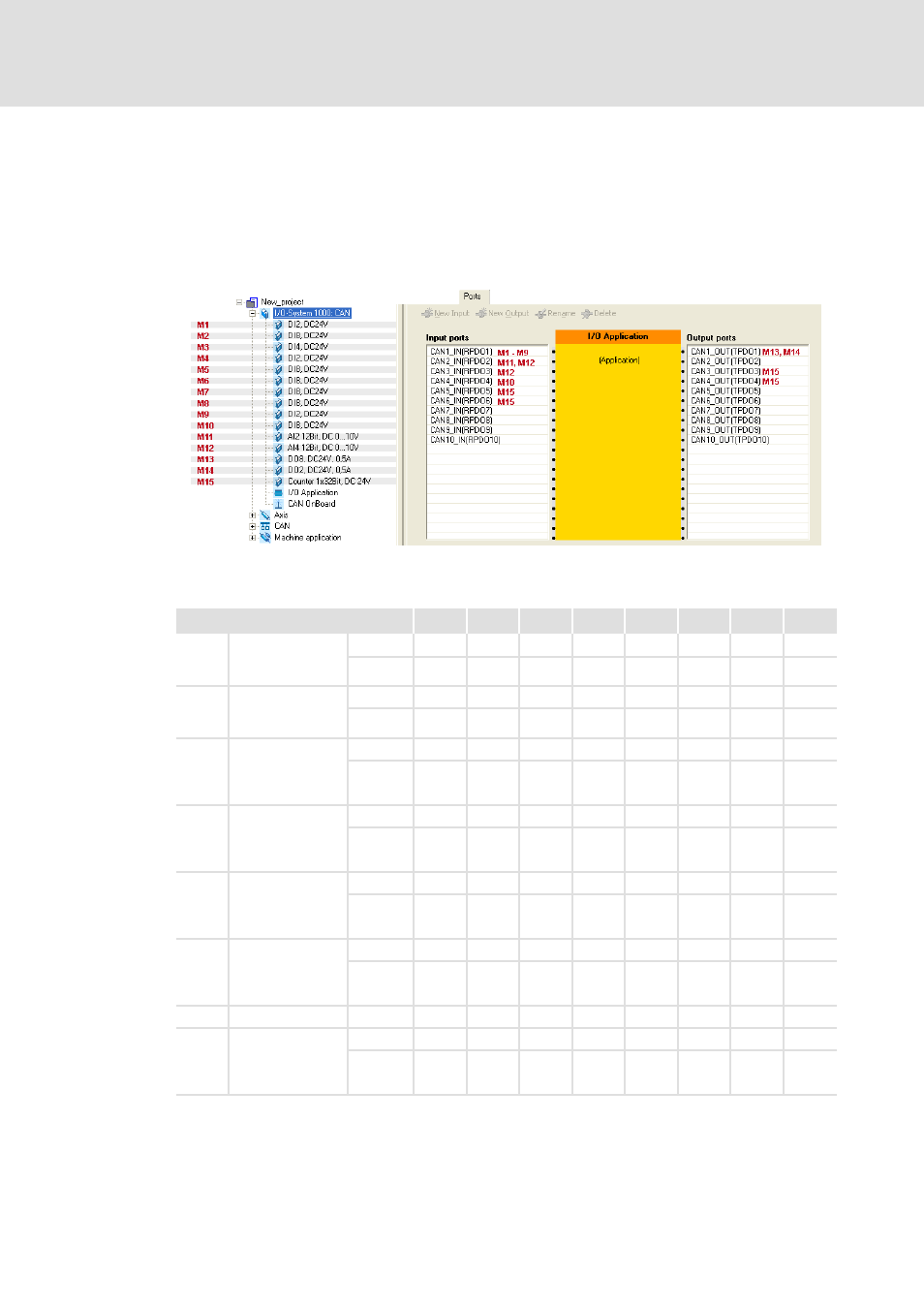
The principle of the PDO mapping can be made clear using the following station structure
as an example:
According to the configured I/O system 1000 in the illustration, the following PDO
mapping arises:
Process image
Byte 0 Byte 1 Byte 2 Byte 3 Byte 4 Byte 5 Byte 6 Byte 7
PDO1
Permanent for the
first
DI or DO
RPDO1
M13
M14
-
-
-
-
-
-
TPDO1
M1
M2
M3M4
M5
M6
M7
M8
M9
PDO2
Permanent for the
first
AI or AO
RPDO2
-
-
-
-
-
-
-
-
TPDO2
M11
M11
M11
M11
M12
M12
M12
M12
PDO3
DI/DO, DI/DO
TimeStamp, DO
PWM, AI/AO,
counter, SSI
RPDO3
M15
M15
M15
M15
M15
M15
M15
M15
TPDO3
M12
M12
M12
M12
-
-
-
-
PDO4
DI/DO, DI/DO
TimeStamp, DO
PWM, AI/AO,
counter, SSI
RPDO4
M15
M15
-
-
-
-
-
-
TPDO4
M10
-
-
-
-
-
-
-
PDO5
DI/DO, DI/DO
TimeStamp, DO
PWM, AI/AO,
counter, SSI
RPDO5
-
-
-
-
-
-
-
-
TPDO5
M15
M15
M15
M15
M15
M15
M15
M15
PDO6
DI/DO, DI/DO
TimeStamp, DO
PWM, AI/AO,
counter, SSI
RPDO6
-
-
-
-
-
-
-
-
TPDO6
M15
M15
M15
M15
-
-
-
-
...
...
...
PDO10 DI/DO, DI/DO
TimeStamp, DO
PWM, AI/AO,
counter, SSI
RPDO10
-
-
-
-
-
-
-
-
TPDO10
-
-
-
-
-
-
-
-