L-force controls | i/o system 1000 – Lenze L-force I/O System 1000 User Manual
Page 42
L-force Controls | I/O System 1000
Parameter setting
Electronic modules - digital output
42
L
2.0 EN - 11/2010
Process data
See also:
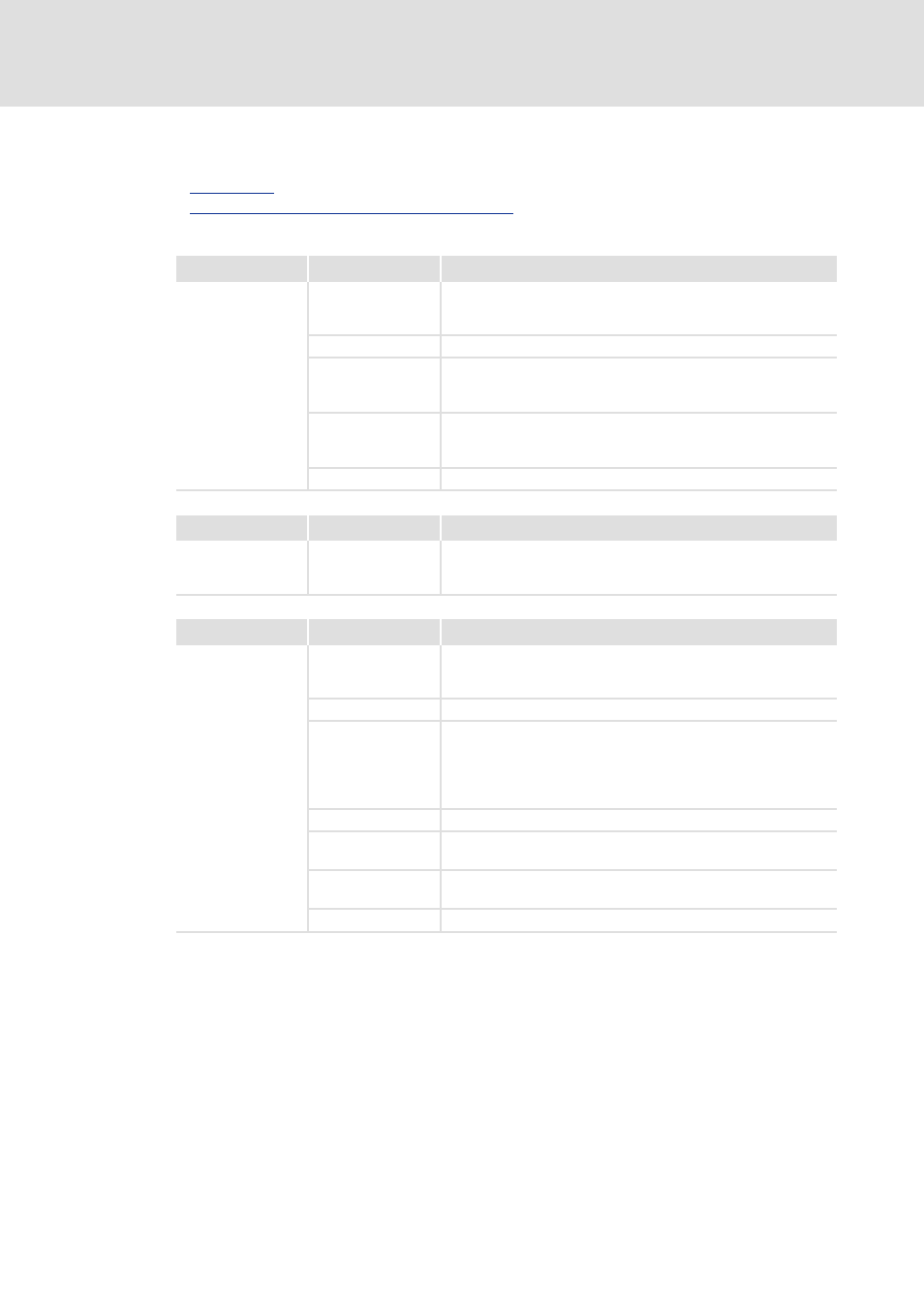
PDO mapping for digital modules with PWM function
Index
Bit
Description
0x5420/x
Status word
• For each electronic module, two subindex entries are created. A
subindex defines a digital output (PWM 1, PWM 2).
0
Reserved
1
PWM status.
• 0: PWM output is stopped
• 1: PWM output is active
2
Output status.
• 0: Push/pull output
• 1: Highside output
3 … 15
Reserved
Index
Bit
Description
0x5620/x
0 … 32
Selection of the pulse duration.
• For each electronic module, two subindex entries are created. A
subindex defines a digital output (PWM 1, PWM 2).
Index
Bit
Description
0x5621/x
Control word
• For each electronic module, two subindex entries are created. A
subindex defines a digital output (PWM 1, PWM 2).
0 … 1
Reserved
2
PWM behaviour.
• 0: Push/pull output
–The output signal is switched to HIGH level and to LOW level.
• 1: Highside output
–The output signal is only switched to HIGH level.
3 … 7
Reserved
8
Start PWM output.
0-1 edge: Starts PWM output
9
Stop PWM output.
1-0 edge: Stops PWM output
10 … 15
Reserved