3 electronic modules - digital output, Electronic modules - digital output ( 36), Electronic modules - digital output – Lenze L-force I/O System 1000 User Manual
Page 36: L-force controls | i/o system 1000
L-force Controls | I/O System 1000
Parameter setting
Electronic modules - digital output
36
L
2.0 EN - 11/2010
6.3
Electronic modules - digital output
6.3.1
"DOx, DC24V" and "DOx NPN, DC24V" electronic modules
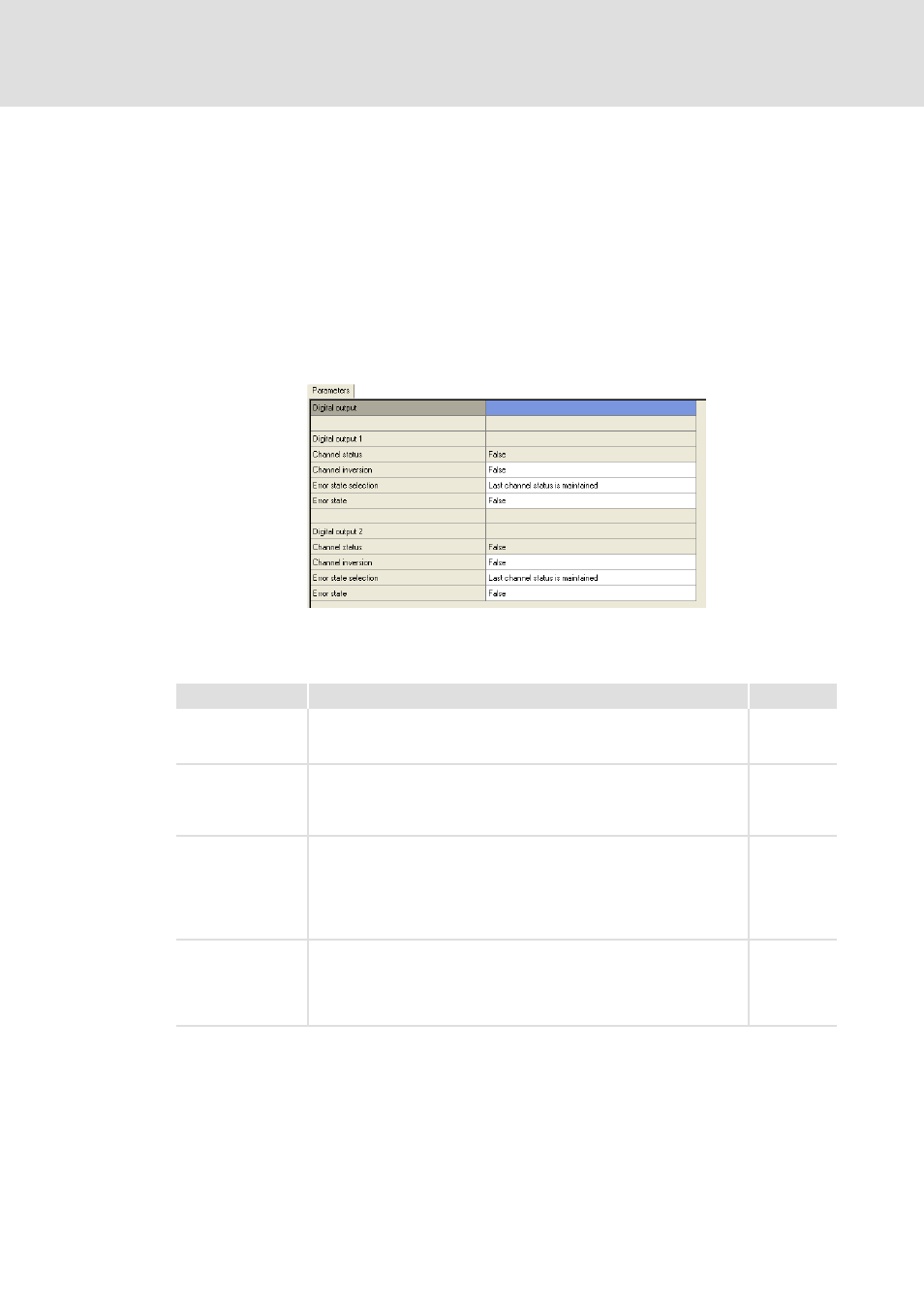
Use the Parameters tab to select the settings for the electronic module. In addition, the
channel status is indicated.
How to parameterise the electronic module:
1. Select the electronic module in the project view.
2. Click the Parameters tab in the workspace.
3. Make settings for each channel.
Legend
Description
Index
Channel status
Display of the current output signal.
• TRUE: Signal level = HIGH
• FALSE: Signal level = LOW
0x6200
Channel inversion
Inversion of the output signal.
Click the input field to open the drop down menu.
• TRUE: The signal is inverted.
• FALSE: The signal is not inverted.
0x6202
Error state selection
Response of the channel to an error.
Click the input field to open the drop down menu.
• Last channel status is maintained
–The output signal remains on the level output last.
• Channel status = status in event of error
–The output signal is set to the level defined in the "Error state".
0x6206
Error state
Response of the channel to an error if the "Channel status = status in event
of error" has been set in the "Error state selection".
Click the input field to open the drop down menu.
• TRUE: The output signal is permanently set to HIGH level.
• FALSE: The output signal is permanently set to LOW level.
0x6207