L-force controls | i/o system 1000 – Lenze L-force I/O System 1000 User Manual
Page 38
L-force Controls | I/O System 1000
Parameter setting
Electronic modules - digital output
38
L
2.0 EN - 11/2010
TimeStamp function, the operating times of the outputs can be exactly calculated up to
1 μs.
Electronic modules with TimeStamp function are equipped with an internal ticker. To
make sure that all tickers always have the same time base, they are synchronised within a
station via the backplane bus of the CAN bus coupler.
The ticker works with a resolution of 1 μs. After power-on, it starts counting from
0 … 65535 μs and then starts with 0 again.
For digital input and output modules with TimeStamp function, both the channel
status and the ticker value are stored in the process image if an edge change of the
signal occurs.
Up to 15 DO switching requests (subindex entries) with TimeStamp function can be
received. Hence, an output can be addressed several times within a cycle.
In the Lenze setting, 2 switching requests are automatically assigned to a PDO.
Additional switching requests can only be supported through manual mapping, e.g.
using the PLC Designer.
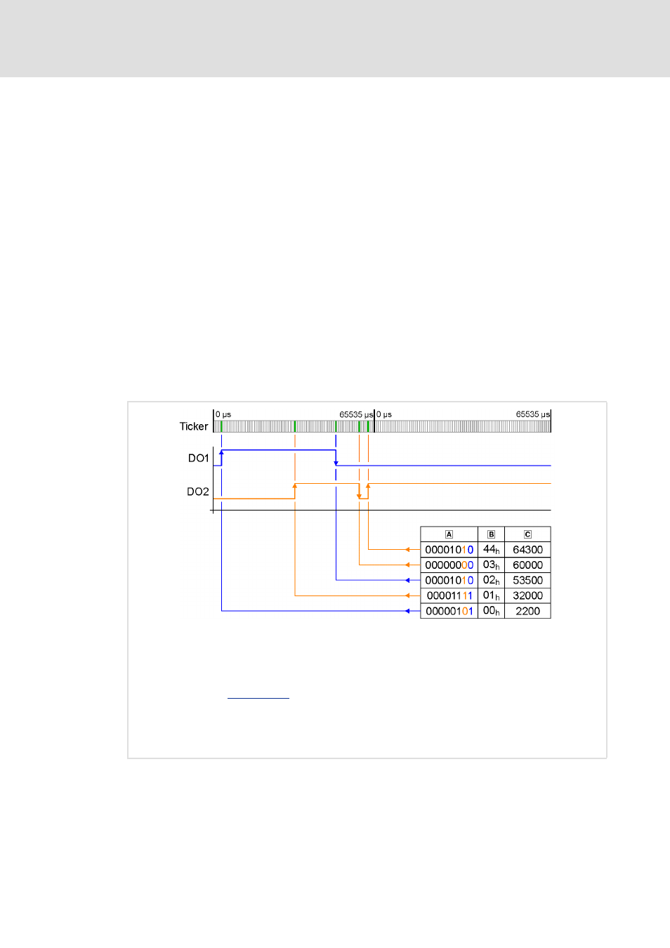
Function
[6-1]
Output of the TimeStamp entries
DO1 Digital output 1
The output signal is switched according to the TimeStamp entry.
DO2 Digital output 2
The output signal is switched according to the TimeStamp entry.
Bit assignment
Running number (RN)
Counts from 0 … 63 and then starts with 0 again. The RN determines the time sequence of the TimeStamp
entries. The RN is incremented with every TimeStamp entry.
Ticker value