4 station behaviour after switch-on, L-force controls | i/o system 1000 – Lenze L-force I/O System 1000 User Manual
Page 13
2.0 EN - 11/2010
L
13
L-force Controls | I/O System 1000
Product description
Station behaviour after switch-on
2.4
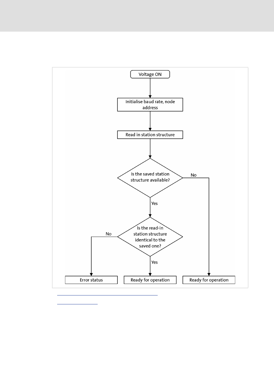
Station behaviour after switch-on
The sequence diagram shows the check routine of the I/O system after every switch-on of
the supply voltage.
See also other documents in the category Lenze Software:
- 9400 (954 pages)
- p300 (195 pages)
- I/O system 1000 (44 pages)
- 3241C (32 pages)
- PC-based automation (60 pages)
- DSD (496 pages)
- PLC Designer R3-x (159 pages)
- Engineer v2.21 (312 pages)
- PLC Designer ApplicationTemplate (PLC Designer R3-x) (177 pages)
- PLC Designer Migration PLC Designer (R2-x)-PLC Designer (R3-x) (30 pages)
- PLC Designer PLC Designer (R2-x) (844 pages)
- PLC Designer PLC Designer (R3-1) (1170 pages)
- PLC Designer PLC Designer (R2-x) CANopen for Runtime Systems (56 pages)
- PLC Designer PLC-Designer (R2-x) SoftMotion (290 pages)
- ApplicationTemplate PackML (PLC Designer R3-x) (99 pages)
- EASY Starter-ApplicationLoader (13 pages)
- ASY Starter Lenze OPC UA-Server (9 pages)
- 8400 motec (518 pages)
- 8400 TopLine (1760 pages)
- i700 (338 pages)
- 8400 HighLine (1576 pages)
- 8400 StateLine (1030 pages)
- 8400 BaseLine C (342 pages)
- 8400 BaseLine D (260 pages)
- E70ACxS Application Sample i700 (PLC Designer v3) (33 pages)
- E94AYFLF Digital frequency module (54 pages)
- E94ARNE Regenerative power supply (360 pages)
- E94AxHE Servo Drives 9400 HighLine (Firmware 01-37) (679 pages)
- E94AxHE Technology Application Actuating drive - Speed (38 pages)
- E94AxHE Technology Application Actuating drive - Torque (34 pages)
- E94AxHE Technology Application CiA402 Device profile (232 pages)
- E94AxHE Technology Application Electronic gearbox (80 pages)
- E94AxHE Technology Application Positioning sequence control (78 pages)
- E94AxHE Technology Application Synchronism (80 pages)
- E94AxHE Technology Application Table positioning (50 pages)
- Loader L-force Loader (45 pages)
- Function library LenzeIO1000Drv (64 pages)
- ETC Motion Control (428 pages)
- Function library CANopenSdoDrv (26 pages)
- Function library LenzeConversionBox (14 pages)
- ACU UPS for Industrial PCs (18 pages)
- PLC Designer V2.x (336 pages)
- IPC Operating System Windows CE Thin Client (26 pages)
- IPC Operating System Windows Embedded Standard 2009 (14 pages)