6 safety manual – JUMO 701150 14597 safetyM STB/STW - Safety Temperature Limiter and Safety Temperature Monitor Operating Manual User Manual
Page 35
6 Safety Manual
35
Important information:
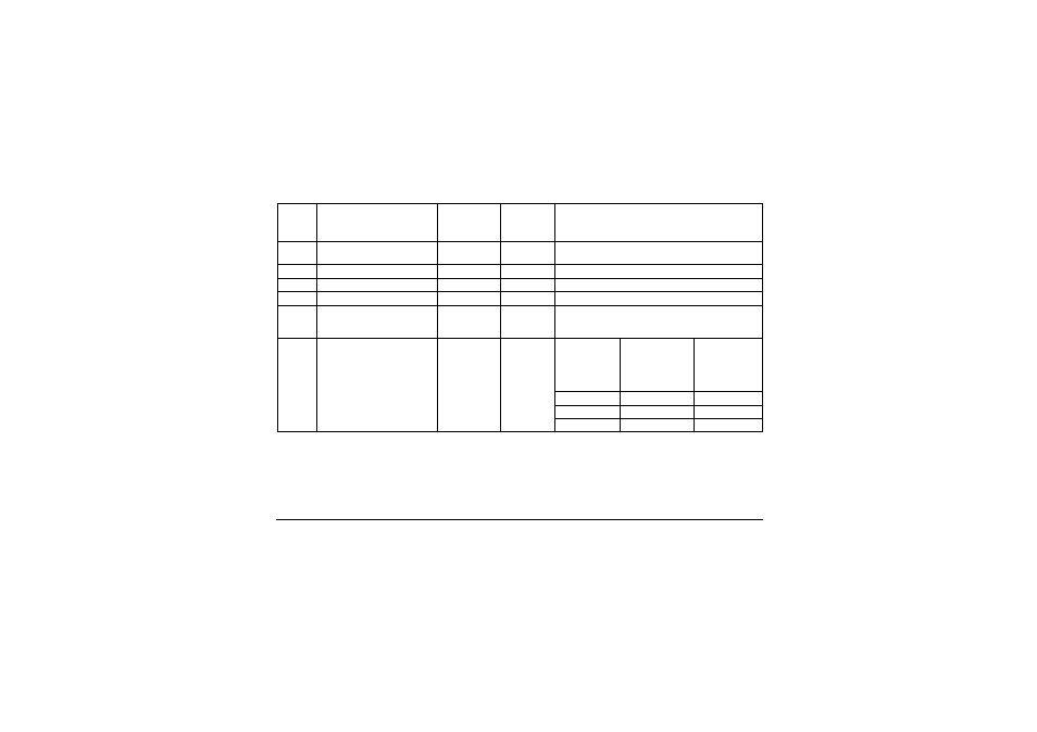
Variants 1 to 4 were evaluated with JUMO probes according to data sheets 901006 and 902006. For variant 5 no sensor sys-
tem was taken into account. In this case, the user selects the sensor system. For this reason, the user is responsible for evalu-
ating the achievable SIL.
If the used SIL-capable sensor consists of hardware and software (e.g. transmitter), the maximum SIL that can be achieved –
irrespective of the architecture – is the one according to which the sensor software was developed (so, for example, if the sen-
sor software has SIL2, the max. achievable SIL is 2).
Variant
Connected sensors
Sensor
system
architecture
Logic
architectur
e
Achievable SIL
1
1 × Pt100 in 2-wire circuit
individual sensor
1oo1
1oo2D
SIL2
1a
2x Pt100/1000 2-wire circuit
1oo2
1oo2D
SIL3
2
2x Pt100/1000 3-wire circuit
1oo2
1oo2D
SIL3
3
2x thermocouple
1oo2
1oo2D
SIL3
4
1x Pt100/1000
2-wire and 3-wire circuit
1x thermocouple
1oo2
1oo2D
SIL3
5
STB/STW 701150 without
sensor system 1oo2D archi-
tecture.
No probe or use 4 to 20 mA
(means that the sensor is not
taken into account for the cal-
culation).
Sensors con-
nected by the
system user
Architecture
acc. to con-
nection 1oo1
or 1oo2
1oo2D
SIL of the used
sensor (HW on-
ly)
Max. achievable
SIL of the system
with 1oo1 sensor
system architec-
ture
Max. achievable
SIL of the sys-
tem with 1oo2
sensor system
architecture
SIL1
SIL1
SIL2
SIL2
SIL2
SIL3
SIL3
SIL3
SIL3