Hardware installation – DATOptic ARC-1680 Series User Manual
Page 37
HARDWARE INSTALLATION
37
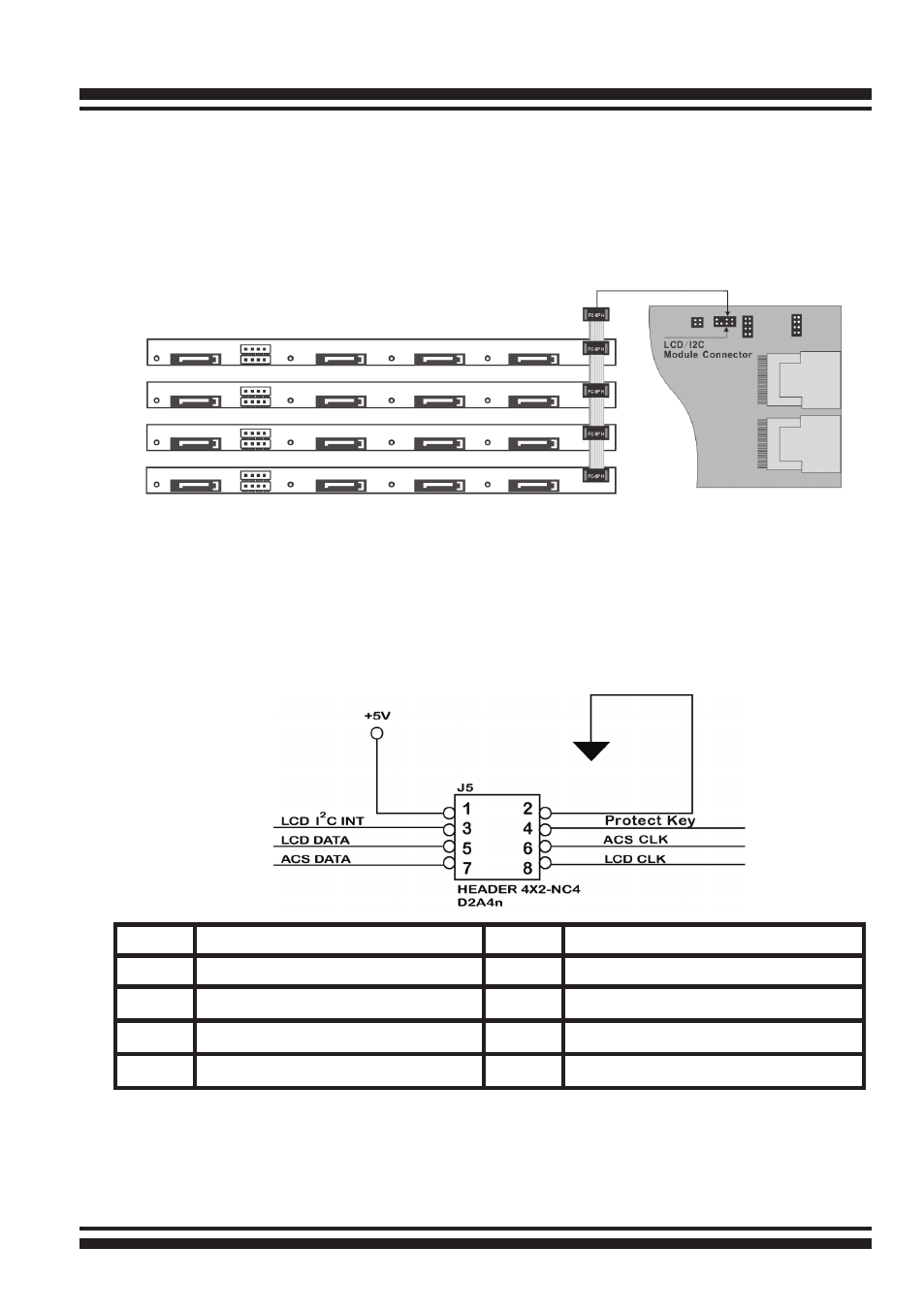
Figure 2-20, Activity/Fault LED I
2
C connector connected between
SAS RAID Controller & 4 SATA HDD backplane.
B: I
2
C Connector
You can also connect the I
2
C interface to a proprietary SAS/SATA
backplane enclosure. This can reduce the number of activity LED
and/or fault LED cables. The I
2
C interface can also cascade to
another SAS/SATA backplane enclosure for the additional channel
status display.
PIN
Description
PIN
Description
1
Power (+5V)
2
GND
3
LCD Module Interrupt
4
Protect Key
5
LCD Module Serial Data
6
Fault/Activity Clock
7
Fault/Activity Serial Data
8
LCD Module Clock
The following picture and table is the I
2
C signal name description
for LCD & fault/activity LED.