Allied Telesis SwitchBlade x8112 User Manual
Page 106
Chapter 4: Installing the Power Supplies
106
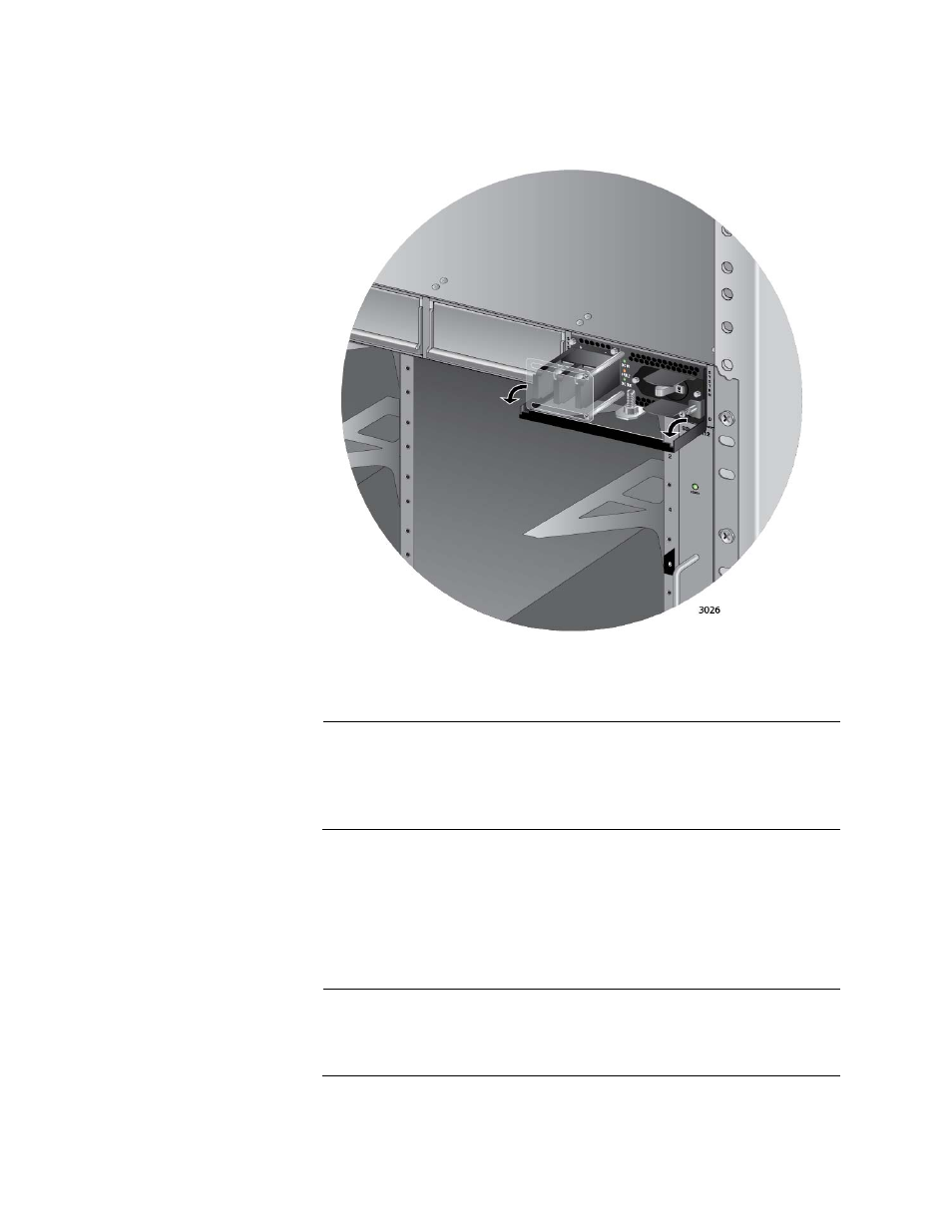
7. Lower the locking handle of the power supply module to secure the
module in the slot, as shown in Figure 61.
Figure 61. Locking the Handle on the AT-SBxPWRSYS1 DC System
Power Supply
Note
Do not tighten the handle locking screw yet. You may need to
slightly lift the handle to move the plastic guard panel when you wire
the positive and negative wires in “Powering On the AT-
SBxPWRSYS1 DC System Power Supply” on page 151.
8. To install a second AT-SBxPWRSYS1 DC System Power Supply,
repeat this procedure.
9. After installing the power supplies, go to Chapter 5, “Installing the AT-
SBx81CFC400 Control Card and Ethernet Line Cards” on page 107.
Note
Retain the five wire ring lugs that come with the power supply. You
use them to wire the power supply in Chapter 7, “Powering On the
Chassis” on page 141.
- AT-GS908M (54 pages)
- AT-x230-10GP (80 pages)
- AT-GS950/48PS (64 pages)
- AT-GS950/10PS (386 pages)
- AT-GS950/16PS (386 pages)
- AT-GS950/48PS (386 pages)
- AT-9000 Series (258 pages)
- AT-9000 Series (1480 pages)
- IE200 Series (70 pages)
- AT-GS950/48 (410 pages)
- AT-GS950/8 (52 pages)
- AT-GS950/48 (378 pages)
- AT-GS950/48 (60 pages)
- SwitchBlade x8106 (322 pages)
- SwitchBlade x8112 (322 pages)
- SwitchBlade x8106 (240 pages)
- AT-TQ Series (172 pages)
- AlliedWare Plus Operating System Version 5.4.4C (x310-26FT,x310-26FP,x310-50FT,x310-50FP) (2220 pages)
- FS970M Series (106 pages)
- 8100L Series (116 pages)
- 8100S Series (140 pages)
- x310 Series (116 pages)
- x310 Series (120 pages)
- AT-GS950/24 (366 pages)
- AT-GS950/16 (44 pages)
- AT-GS950/24 (404 pages)
- AT-GS950/16 (404 pages)
- AT-GS950/16 (364 pages)
- AT-GS950/8 (404 pages)
- AT-GS950/8 (364 pages)
- AT-GS950/8 (52 pages)
- AT-8100 Series (330 pages)
- AT-8100 Series (1962 pages)
- AT-FS970M Series (330 pages)
- AT-FS970M Series (1938 pages)
- SwitchBlade x3106 (288 pages)
- SwitchBlade x3112 (294 pages)
- SwitchBlade x3106 (260 pages)
- SwitchBlade x3112 (222 pages)
- AT-S95 CLI (AT-8000GS Series) (397 pages)
- AT-S94 CLI (AT-8000S Series) (402 pages)
- AT-IMC1000T/SFP (23 pages)
- AT-IMC1000TP/SFP (24 pages)
- AT-SBx3106WMB (44 pages)