7 tipping bucket rain gauge with long leads, 8 100 ohm prt in 4 wire half bridge – Campbell Scientific CR23X Micrologger User Manual
Page 93
SECTION 7. MEASUREMENT PROGRAMMING EXAMPLES
7-5
PROGRAM
1: Pulse (P3)
1:
1
Reps
2:
1
Pulse Channel 1
3:
20
High Frequency, Output Hz
4:
1
Loc [ WS_m_s ]
5:
.0979
Mult
6:
.2
Offset
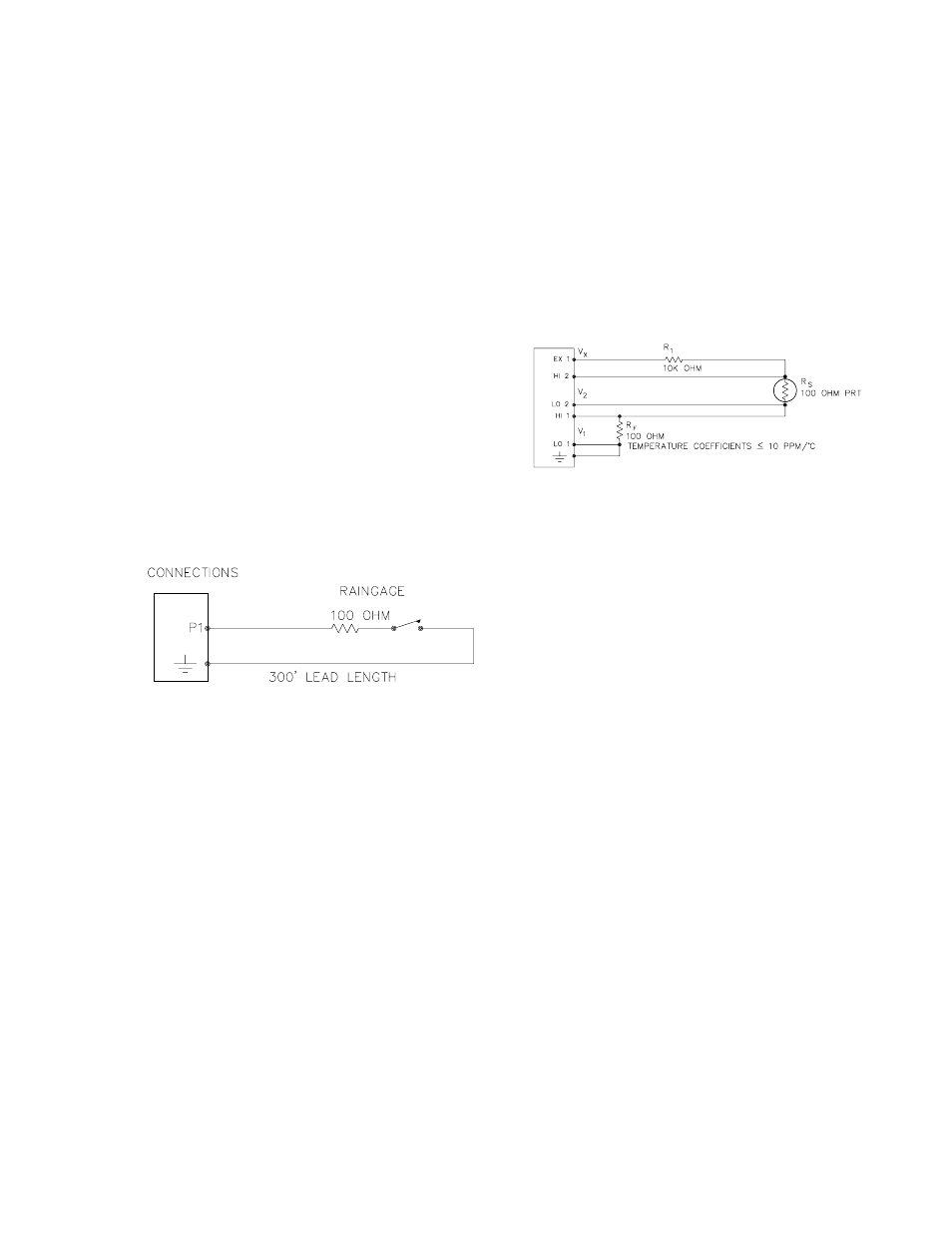
7.7 TIPPING BUCKET RAIN GAUGE
WITH LONG LEADS
A tipping bucket rain gauge is measured with
the Pulse Count Instruction configured for Switch
Closure. Counts from long intervals will be used
(an option in Parameter 3), as the final output
desired is total rainfall (obtained with Instruction
72, Totalize). If counts from long intervals were
discarded, less rainfall would be recorded than
was actually measured by the gauge (assuming
there were counts in the long intervals). Output
is desired in millimeters of precipitation. The
gauge is calibrated for a 0.01 inch tip; a
multiplier of 0.254 is used.
CR23X
FIGURE 7.7-1. Wiring Diagram for Rain
Gauge with Long Leads
In a long cable there is appreciable capacitance
between the lines, which is discharged across
the switch when it closes. In addition to
shortening switch life, a transient may be
induced in other wires, packaged with the rain
gauge leads, each time the switch closes. The
100 ohm resistor protects the switch from arcing
and the associated transient from occurring, and
should be included any time leads longer than
100 feet are used with a switch closure.
PROGRAM
1: Pulse (P3)
1:
1
Reps
2:
1
Pulse Channel 1
3:
2
Switch Closure, All Counts
4:
1
Loc [ InchRain ]
5:
.254
Mult
6:
0.0
Offset
7.8 100 OHM PRT IN 4 WIRE HALF
BRIDGE
Instruction 9 is the best choice for accuracy
where a 100 ohm Platinum Resistance
Thermometer (PRT) is separated from other
bridge completion resistors by a lead length
having more than a few thousandths of an ohm
resistance. In this example, it is desired to
measure a temperature in the range of -10 to
40
o
C. The length of the cable from the CR23X
to the PRT is 500 feet.
CR23X
FIGURE 7.8-1. Wiring Diagram for PRT in 4
Wire Half Bridge
Figure 7.8-1 diagrams the circuit used to
measure the PRT. The 10 kohm resistor allows
the use of a high excitation voltage and a low
input range. This insures that noise in the
excitation does not have an effect on signal
noise. Because the fixed resistor (R
f
) and the
PRT (R
s
) have approximately the same
resistance, the differential measurement of the
voltage drop across the PRT can be made on
the same range as the differential measurement
of the voltage drop across R
f
. The use of the
same range eliminates any range translation
error that might arise from the 0.01% tolerance
of the range translation resistors in the CR23X.
If the voltage drop across the PRT (V
2
) is kept
on the 50mV range, self heating of the PRT
should be less than 0.001
o
C in still air. The
resolution of the measurement is increased as
the excitation voltage (V
x
) is increased as long
as the Input Range is not exceeded. The
voltage drop across the PRT is equal to V
x
multiplied by the ratio of R
s
to the total
resistance, and is greatest when R
s
is greatest
(R
s
=115.54 ohms at 40
o
C). To find the
maximum excitation voltage that can be used,
we assume V
2
equal to 50mV and use Ohm's
Law to solve for the resulting current, I.