4 modem/terminal peripherals, 5 synchronous device communication – Campbell Scientific CR23X Micrologger User Manual
Page 82
SECTION 6. 9-PIN SERIAL INPUT/OUTPUT
6-4
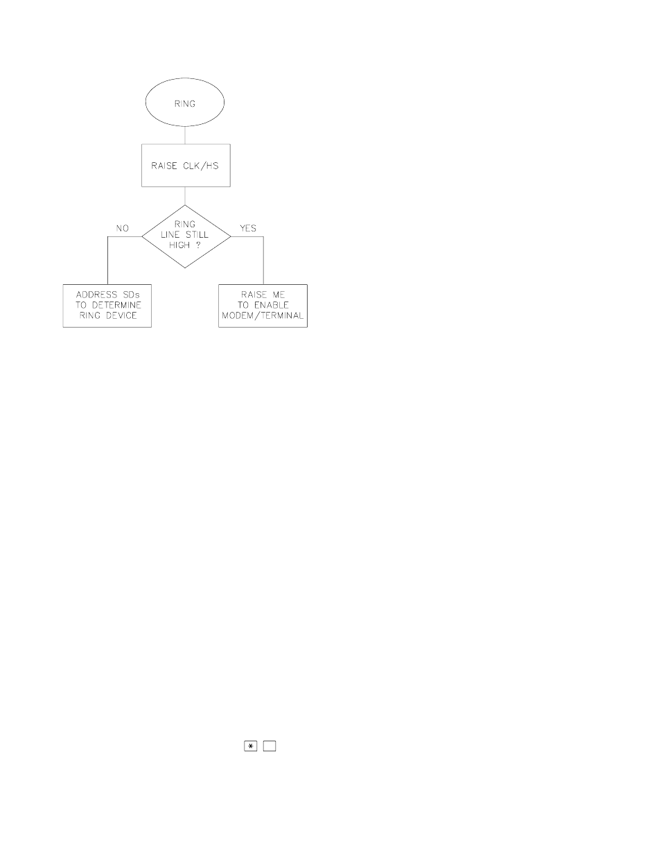
FIGURE 6.2-3. Servicing of Ring Interrupts
6.2.4 MODEM/TERMINAL PERIPHERALS
The CR23X considers any device with an
asynchronous serial communications port which
raises the Ring line (and holds it high until the
ME line is raised) to be a modem peripheral.
Modem/terminals include Campbell Scientific
phone modems, and most computers,
terminals, and modems using the SC32A
Optically Isolated RS-232 Interface, the SC932
RS-232 DCE Interface, or the SC929 cable.
When a modem raises the Ring line, the CR23X
responds by raising the ME line. The CR23X
must then receive carriage returns spaced at
least 50 ms apart until it can establish baud rate.
When the baud rate has been set, the CR23X
sends a carriage return, line feed, "
∗
".
The ME line is held high until the CR23X receives
an "E" to exit telecommunications. The ME is
also lowered if a character is not received after 40
seconds in the Telecommunications Command
State (2 minutes in the Remote Keyboard State).
Some modems are quite noisy when not on line; it
is possible for valid characters to appear in the
noise pattern. For this reason, the CR23X counts
all the invalid characters it receives from the time
it answers a ring, and terminates communication
(lowers the ME line and returns to the
0
Mode) after receiving 150 invalid characters.
6.2.5 SYNCHRONOUS DEVICE
COMMUNICATION
Synchronous Devices (SDs) differ from enabled
peripherals (Section 6.2.1) in that they are not
enabled solely by a hardware line. An SD is
enabled by an address synchronously clocked
from the CR23X. Up to 16 SDs may be
addressed by the CR23X, requiring only three
pins of the 9-pin connector.
Synchronous Device Communication (SDC)
discussed here is for those peripherals which
connect to the 9-pin serial port. This should not
be confused with Synchronous Device for
Measurement (SDM) peripherals connected to
control ports 1, 2, and 3. (Although the
communication protocol for SDMs is very
similar, their addressing is independent of SDC
addresses and they do not have a ring line.)
SD STATES
The CR23X and the SDs use a combination of
the Ring, Clock Handshake (CLK/HS) and
Synchronous Device Enable (SDE) lines to
establish communication. The CR23X can put
the SDs into one of six states.
STATE 1, the SD Reset State
The CR23X forces the SDs to the reset/request
state by lowering the SDE and CLK/HS lines.
The SD cannot drive the CLK/HS or RXD lines
in State 1, however, it can raise the Ring line if
service is needed. The SD can never pull the
Ring low if a Modem/Terminal is holding it high.
Data on TXD is ignored by the SD.
STATE 2, the SD Addressing State
The CR23X places the SDs in the addressing
state by raising CLK/HS followed by or
simultaneously raising SDE (Figure 6.2-4). TXD
must be low while SDE and CLK/HS are
changing to the high state.
State 2 requires all SDs to drop the Ring line
and prepare for addressing. The CR23X then
synchronously clocks 8 bits onto TXD using
CLK/HS as a clock. The least significant bit is
transmitted first and is always logic high. Each
bit transmitted is stable on the rising edge of
CLK/HS. The SDs shift in bits from TXD on the
rising edge of CLK/HS provided by the CR23X.
The CR23X can only address one device per
State 2 cycle. More than one SD may respond