B.3 instruction 15 and parameter descriptions, Parameter 1 - repetitions, Parameter 2 - configuration code – Campbell Scientific CR23X Micrologger User Manual
Page 246
APPENDIX B. CONTROL PORT SERIAL I/O INSTRUCTION 15
B-2
CR23X
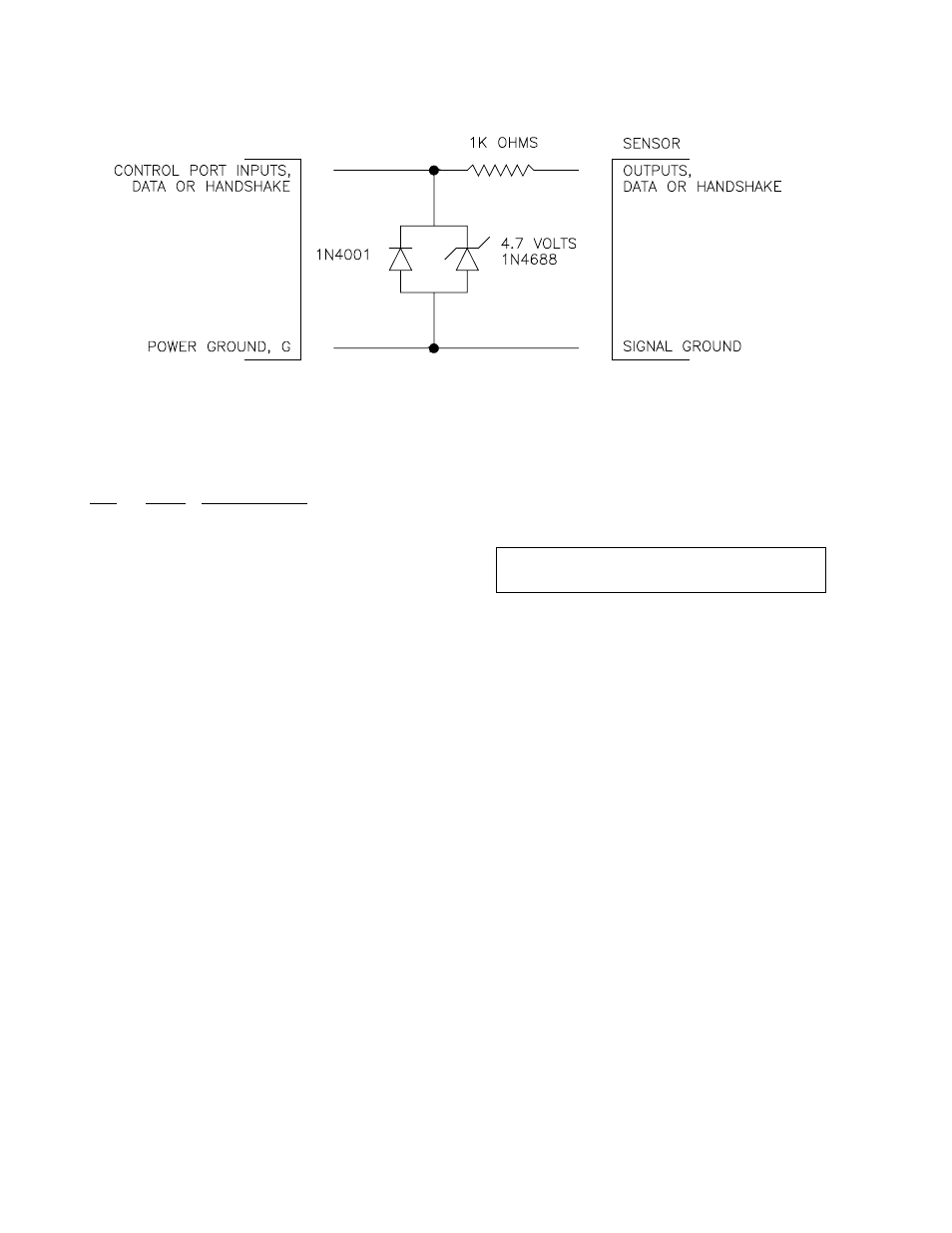
FIGURE B-1. Circuit To Limit Input to 0 to 5 Volts
B.3 INSTRUCTION 15 AND
PARAMETER DESCRIPTIONS
PAR.
DATA
NO. TYPE
DESCRIPTION
01:
2
Repetitions
02:
2
Configuration code (xy)
03:
4
CTS / Delay before send
0 = Wait for Clear to Send
>0 = delay (.01 secs)
04:
2
Control ports (AB)
05:
4
Output start Loc
06:
4
Number of locations to send
0 = send nothing
xxxx = locations; preamble
xxxx-- = locations; data
07:
4
Input termination character
(0..255)
08:
4
Maximum number of input
characters
09:
4
Delay for CTS and/or
Input (.01 secs)
10:
4
Input start location
11:
FP
Multiplier
12:
FP
Offset
INPUT LOCATIONS ALTERED determined by input
INTERMEDIATE LOCATIONS USED preamble
size/4 + 1
EXECUTION TIME
If Parameters 3 and 6 are zero (0), maximum
execution time is Parameter 9 times 0.01
seconds (input time out).
If Parameter 3 is 0 and 6 is not 0, maximum
time is Parameter 9 times 0.01 secs times 2
(CTS and input time outs).
If Parameter 8 is 0 (no input), maximum time is
Parameter 3 times .01 secs, or Parameter 9
times .01 secs if Parameter 3 = 0.
Add [10 bits/X bits/second] per byte output
X can equal 300, 1200, 2400, 4800, 9600, 19200,
38400, 76800
NOTE: Times are shorter if CTS and/or data
input is done before Parameter 9 time out.
PARAMETER 1 - REPETITIONS
Parameter 1 specifies the number of sensors
that can be read using the same Instruction 15
parameter configuration. For example, a REP
of 3 is used for 3 identical sensors or 3 sensors
that are satisfied by the same parameter
configuration. Instruction 15 must be entered
separately for each sensor or group of sensors
requiring a different configuration. A maximum
of either 2 or 4 repetitions are possible
depending on the configuration.
The CR23X sequentially increments sets of
control ports and input locations with each
repetition. The number of control ports used for
each repetition (2, 3 or 4) depends on whether
data is to be output and/or input, and the
number of lines used to control the timing
(Refer to Section B4, "Control Port
Configurations and Sensor Wiring").
The starting output location specified in
Parameter 5 is used for all repetitions.
PARAMETER 2 - CONFIGURATION CODE
The configuration code is a two-digit number
specifying the input format, logic level, baud
rate, buffering option, and optional decimal
delimiter. Index (--) this parameter to indicate
that you do not want to buffer received data.