Cr23x micrologger, Ref_temp +21.93 – Campbell Scientific CR23X Micrologger User Manual
Page 234
SECTION 14. INSTALLATION AND MAINTENANCE
14-8
H
L
1
2
1
H
L
3
4
2
H
L
5
6
3
H
L
7
8
4
H
L
9
10
5
H
L
11
12
6
DIFF
SE
H
L
13
14
7
H
L
15
16
8
H
L
17
18
9
H
L
19
20
40
H
L
21
22
11
H
L
23
24
12
DIFF
SE
EX1
EX2
EX3
EX4
CAO1
CAO2
P1
P2
P3
P4
G
5V
G
SW12
G
12V
12V
G
C1
C2
C3
C4
G
C5
C6
C7
C8
G
POWER OUT
CONTROL I/O
POWER IN
CAUTION
DC ONLY
G 12V
GROUND
LUG
SDM
CS I/O
COMPUTER
RS232
(OPTICALLY ISOLATED)
1
2
3
A
4
5
6
B
7
8
9
C
*
0
#
D
MADE IN USA
SN:
CR23X MICROLOGGER
04:REF_TEMP
+21.93
Ground Plane
Excitation, CAO, Pulse-Counter
Grounds ( )
Power
Grounds (G)
To CR23X
Electronics
1.85A
Thermal Fuse
On/Off
Batteries
5A
Thermal
Fuse
G
1.5k E20A
10 F
12V
SW12
Control
0.9A
Ther
mal Fuse
1.85A
Ther
mal Fuse
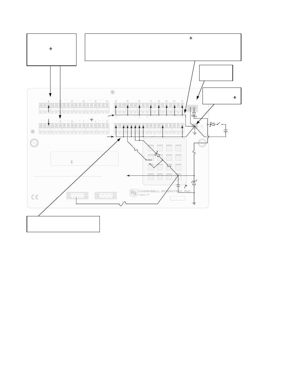
FIGURE 14.7-1. Schematic of CR23X Grounds
The 9-pin serial I/O ports on the CR23X are
another path for transients to enter and damage
the CR23X. Communications devices such a
telephone or short-haul modem lines should
have spark gap protection. Spark gap
protection is often an option with these
products, so it should always be requested
when ordering. The spark gaps for these
devices must be connected to either the CR23X
earth ground lug, the enclosure ground, or to
the earth (chassis) ground.
A good earth (chassis) ground will minimize
damage to the datalogger and sensors by
providing a low resistance path around the
system to a point of low potential. Campbell
Scientific recommends that all dataloggers in
use be earth (chassis) grounded. All
components of the system (dataloggers,
sensors, external power supplies, mounts,
housings, etc.) should be referenced to one
common earth (chassis) ground.
In the field, at a minimum, a proper earth
ground will consist of a 6 to 8 foot copper
sheathed grounding rod connected to the
CR23X Ground Lug with a 12 AWG wire. In low
conductive substrates, such as sand, very dry
soil, ice, or rock, a single ground rod will
probably not provide an adequate earth ground.
Tie analog signal
shields and returns to
grounds (
) located
in analog input
terminal strips.
Tie CAO and pulse-counter returns into grounds (
) in CAO and pulse-
counter terminal strip. Large excitation return currents may also be tied
into this ground in order to minimize induced single-ended offset voltages
in half bridge measurements.
External
Power Input
Tie 5 V, SW12, 12 V and C1-C8
returns into power grounds (G).
Star Ground at
Ground Lug