1 the input settling time constant – Campbell Scientific CR23X Micrologger User Manual
Page 204
SECTION 13. CR23X MEASUREMENTS
13-4
13.3 THE EFFECT OF SENSOR LEAD
LENGTH ON THE SIGNAL SETTLING
TIME
Whenever an analog input is switched into the
CR23X measurement circuitry prior to making a
measurement, a finite amount of time is
required for the signal to stabilize at its correct
value. The rate at which the signal settles is
determined by the input settling time constant
which is a function of both the source
resistance, and input capacitance (explained
below). The CR23X allows a 450 µs settling
time before initiating the measurement. In most
applications this settling time is adequate, but
the additional wire capacitance associated with
long sensor leads can increase the settling time
constant to the point that measurement errors
may occur. There are three potential sources of
error which must settle before the measurement
is made:
1.
The signal must rise to its correct value.
2.
A transient (
~
30 mV on an open channel)
due to charge injection of the multiplexed
analog inputs, must settle.
3.
A larger transient, usually about 40 mV/V,
caused by the switched, precision excitation
voltage used in resistive bridge
measurements must settle.
The purpose of this section is to bring attention
to potential measurement errors caused when
the input settling time constant gets too large
and to discuss procedures whereby the effects
of lead length on the measurement can be
estimated. In addition, physical values are given
for three types of wire used in CSI sensors, and
error estimates for given lead lengths are
provided. Finally, techniques are discussed for
minimizing input settling error when long leads
are mandatory.
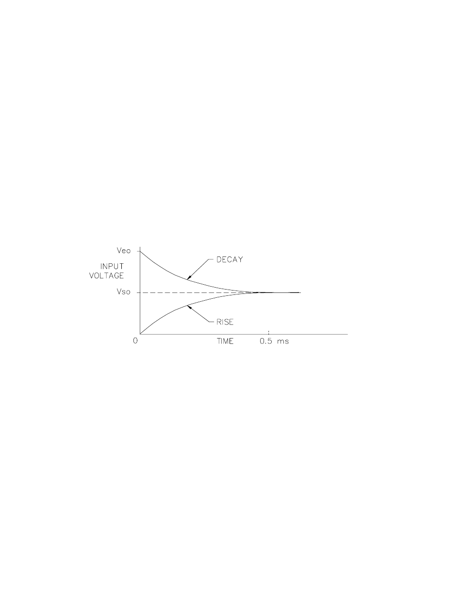
FIGURE 13.3-1. Input Voltage Rise and Transient Decay
13.3.1 THE INPUT SETTLING TIME CONSTANT
The rate at which an input voltage rises to its full
value or that a transient decays to the correct
input level are both determined by the input
settling time constant. In both cases the
waveform is an exponential. Figure 13.3-1
shows both a rising and decaying waveform
settling to the signal level, Vso. The rising input
voltage is described by Equation 13.3-1 and the
decaying input voltage by Equation 13.3-2.
V
s
= V
so
(1-e-t/R
o
C
T
), rise
[13.3-1]
V
s
= V
so
+ (V
eo
-V
so
) e-t/R
o
C
T
, decay
[13.3-2]
where V
s
is the input voltage, V
so
the true signal
voltage, V
eo
the peak transient voltage, t is time
in seconds, R
o
the source resistance in ohms,
and C
T
is the total capacitance between the
signal lead and ground (or some other fixed
reference value) in farads.
The settling time constant,
τ
in seconds, and the
capacitance relationships are given in
Equations 13.3-3 through 13.3-5,
τ
= R
o
C
T
[13.3-3]
C
T
= C
f
+ C
w
L
[13.3-4]
C
f
= 3.3 nfd
[13.3-5]
where C
f
is the fixed CR23X input capacitance
in farads, C
w
is the wire capacitance in
farads/foot, and L is the wire length in feet.
Equations 13.3-1 and 13.3-2 can be used to
estimate the input settling error, V
e
, directly.