Campbell Scientific CR23X Micrologger User Manual
Page 136
SECTION 9. INPUT/OUTPUT INSTRUCTIONS
9-2
CR23X
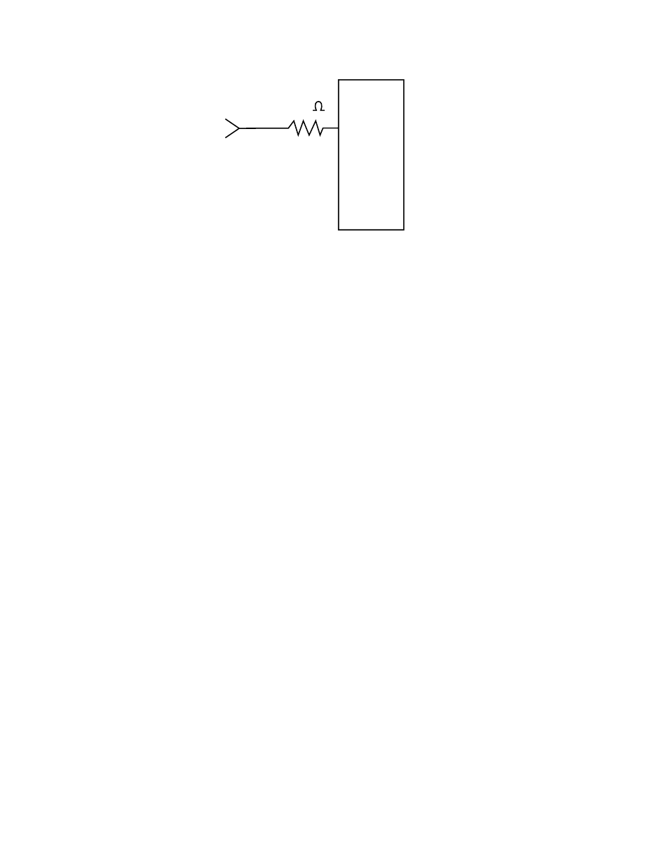
Pi
20k
FIGURE 9-1. Conditioning Large Voltage Pulses
Use separate Pulse Count Instructions when
measuring both pulse channels and control
ports. All Pulse Count instructions must be kept
in the same program table. If the Pulse Count
Instruction is contained within a subroutine, that
subroutine must be called from Table 2.
The use of control ports for pulse measurement
causes the CR23X to use a continuous 10 mA
of power.
Input Voltage
Excessive pulse voltage inputs can damage the
CR23X. Refer to Figure 9-1 if reducing input
voltage is required.
•
Pulse
Channels
Maximum Input Voltage:
±
20 V
•
Control
Ports
Maximum Input Voltage: 5.0 V
High Frequency Input
•
Pulse
Channels
Minimum Pulse Width: 1.2 microsecond
Maximum Frequency: 25 kHz
(8 Bit Counter, 50% Duty Cycle,
0.015 execution interval)
Maximum Frequency: 400 kHz
(16 Bit Counter 50% Duty Cycle)
Lower Threshold: 1.5 V*
Upper Threshold: 3.5 V*
When a pulse channel is configured for
high-frequency pulse, there is an internal
100 kohm pull-up resistor to 5 V on the
pulse channel. This pull-up resistor
accommodates open-collector output
devices for high-frequency input.
•
Control Ports (C5-C8)
Minimum Pulse Width: 150
η
s
Maximum Frequency: 2.5 kHz
Triggered off Rising Edge
-99999 displayed if maximum exceeded
Lower Threshold: 1.5 V
Upper Threshold: 3.5 V
*Larger input transitions are required at high
frequencies because of the input RC filter with
1.2 microsecond time constant. Signals up to
400 kHz will be counted if centered around +2.5
V with deviations
≥
±
2.5 V for
≥
1.2
microseconds.
Low Level AC (Pulse Channels Only)
Input Hysteresis: 15 mV
Maximum Input Voltage: 20 V peak-to-
peak
Input Voltage and Frequency Range
(16 bit counter required above 2.56 kHz)
20 mV
1.0 Hz to 1 kHz
200 mV
0.5 Hz to 10 kHz
1000 mV
0.3 Hz to 16 kHz
Switch Closure
•
Pulse
Channels
A switch closure is connected between
P1..P4 and analog ground. When the
switch is open, the CR23X pulls the
pulse channel to 5 V through a 100
kOhm impedance. When the switch is
closed, the pulse channel is pulled to
ground. The count is incremented
when the switch opens.
Minimum Switch Closed Time: 5 ms
Minimum Switch Open Time: 6 ms
Maximum Bounce Time: 1 ms open
without being counted