Dual rs-485 module dsi486, version a, Figure 65, Dual rs-485 module wiring diagram – Vaisala Hydromet Data Collection Platform User Manual
Page 145: Table 33, Jumper settings for channel b in the rs-485 mode
Chapter 5 ____________________________________________________________ Technical Data
VAISALA______________________________________________________________________ 143
Dual RS-485 Module DSI486,
Version A
Channel A is always used in the RS-485 mode. In 2-wire RS-485, both
transmitted and received data is sent via this channel. In 4-wire RS-485,
this channel can either transmit or receive depending on the
configuration. Jumper X4 defines the line terminating resistor for the
data channel A. Remove the jumper X4 if you do not need the
terminating resistor of the dual RS-485 module.
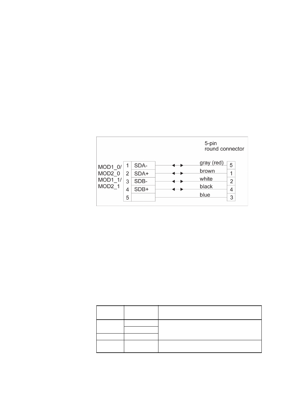
provides a schematic wiring diagram for dual RS-485.
1006-101
Figure 65
Dual RS-485 Module Wiring Diagram
Channel B can be used either in the RS-485 mode or in the RS-232
mode. In 2-wire RS-485, both transmitted and received data is sent via
this channel. In 4-wire RS-485, this channel can either transmit or
receive depending on the configuration.
provides a schematic wiring diagram for the dual
RS-485 connection, the dual 2-wire connection utilizing both channels.
The correct jumper settings for the channel B are listed in
. The jumpers are located on the module as illustrated in
.
Table 33
Jumper Settings for Channel B in the RS-485 Mode
Jumper
Connected
Pins
Function
X3
1-2
Sets the RS-485 mode active for the channel
B.
3-4
X6
1-2
X5
1-2
The line terminating resistor is in use with RS-
485.