Isolated rs-485 module dsi485, Figure 64, Isolated rs-485 module wiring diagram – Vaisala Hydromet Data Collection Platform User Manual
Page 144
User's Guide ______________________________________________________________________
142 __________________________________________________________________M210784EN-E
Isolated RS-485 Module DSI485
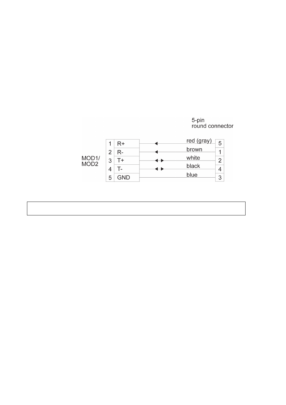
The isolated RS-485 communication module can be configured either
for a 2-wire line or for a 4-wire line when the receive and transmit lines
are separated. If the module is configured for a 2-wire line, the
transmitter is enabled only during the transmission. Normally, the 2-
wire connection is used to connect several devices to the same
communication line. The 4-wire mode is the default mode.
1006-100
Figure 64
Isolated RS-485 Module Wiring Diagram
NOTE
In 2-wire mode, only T+ and T- pins are used.