Ag Leader ParaDyme Radio Option Kits Hardware Installation Guide User Manual
Page 48
42
Radio Option Kits
ParaDyme Smart Antenna Bottom Cover Installation Procedure
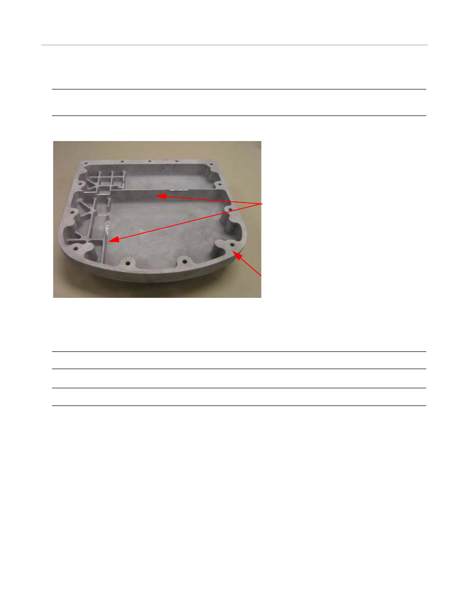
4. Inspect the bottom cover and verify that the flat area where the gasket will touch is clean and free of defects.
Note: Notice the internal walls on the bottom cover. Prior to installing the cover, verify no cables will be pinched by
the walls when it is attached.
Figure 4-46 ParaDyme Receiver Bottom Section Groove Inspection
5. Place the bottom cover on the ParaDyme receiver using the screw holes to guide the cover into the proper position.
6. Verify that the bottom cover is seated properly; there should be a small uniform gap along the seam between the cover and
the ParaDyme receiver.
Note: Make sure the gasket seats properly in its groove and does not get squeezed between the base and the cover.
Note: Ensure that the mating surfaces are clean.
7. Refer to Figure 4-47 for hole number identifications for the following steps.
8. Install three M5 x 12mm screws loosely into holes 5, 7, and 9.
9. Install two M5 x 55mm screws loosely into holes 13 and 10.
10. Install eight M5 x 45mm screws loosely in the remaining holes.
Internal Walls
Flat Area
- Yield Monitor 2000 Operators Manual (202 pages)
- Yield Monitor 2000 Quick Reference Sheets (2 pages)
- PF3000 Harvest & Application Operators Manual (259 pages)
- PF3000 Cotton Yield Monitor Operators Manual (149 pages)
- PF3000/PF3000Pro Harvest Master Mode Operators Manual (13 pages)
- PF3000/PF3000Pro Advanced Light Bar Operators Manual (59 pages)
- PF3000/PF3000Pro Harvest Mode Quick Reference Sheets (2 pages)
- PF3000/PF3000Pro Cotton Harvest Quick Reference Sheets (2 pages)
- PF3000/PF3000Pro Site Verification Mode Quick Reference Sheets (2 pages)
- PF3000/PF3000Pro Rawson Accu-Rate Direct Drive Quick Reference Sheets (9 pages)
- PF3000/PF3000Pro Rawson and New Leader Controllers Quick Reference Sheets (4 pages)
- PF3000/PF3000Pro Raven Controllers (with serial port) Quick Reference Sheets (4 pages)
- PF3000/PF3000Pro Raven Controllers (without serial port) Quick Reference Sheets (3 pages)
- PF3000/PF3000Pro Mid-Tech Controllers Quick Reference Sheets (4 pages)
- PF3000/PF3000Pro Dickey-john Land Manager Quick Reference Sheets (4 pages)
- PF3000/PF3000Pro Dickey-john Seed Manager Quick Reference Sheets (3 pages)
- PF3000/PF3000Pro Hiniker 8100 and 8150 Controllers Quick Reference Sheets (3 pages)
- PF3000/PF3000Pro Hiniker 8605 Controller Quick Reference Sheets (4 pages)
- PF3000/PF3000Pro TeeJet 844 Controller Quick Reference Sheets (4 pages)
- PF3000/PF3000Pro Flexicoil Flex Control Quick Reference Sheets (4 pages)
- PF3000/PF3000Pro Microtrack MT9000/Hardi 3500 Controllers Quick Reference Sheets (4 pages)
- PF3000/PF3000Pro Krohne Flow Meter Quick Reference Sheets (3 pages)
- PF3000/PF3000Pro Shaft Speed Sensor Quick Reference Sheets (3 pages)
- PF3000Pro Harvest & Application Operators Manual (294 pages)
- PF3000Pro Cotton Yield Monitor Operators Manual (168 pages)
- PFadvantage Harvest & Application Operators Manual (264 pages)
- PFadvantage Cotton Yield Monitor Operators Manual (166 pages)
- InSight Harvest Mode (4 pages)
- InSight Site Verification Mode (4 pages)
- InSight Tillage Mode (8 pages)
- InSight Flow Meter (9 pages)
- InSight Spinner Spreader (14 pages)
- InSight Strip-Till (10 pages)
- InSight NORAC UC5 (4 pages)
- InSight Direct Injection (4 pages)
- InSight Rawson and New Leader Controllers (5 pages)
- InSight Raven Serial, NL Mark V, SP6 (5 pages)
- InSight Mid-Tech Controllers (5 pages)
- InSight Direct Command Liquid (19 pages)
- Integra DirectCommand Clutch Control Quick Reference Guides (1 page)
- InSight SC Hydraulic Seed Rate Control (4 pages)
- InSight SC Stepper Seed Rate Control (3 pages)
- InSight SC KINZE PMM (3 pages)
- InSight SC Seed Tube Monitor (STMM) (16 pages)
- InSight Ver.8.0 Users Manual (342 pages)