Ag Leader ParaDyme Radio Option Kits Hardware Installation Guide User Manual
Page 23
Hardware Installation Guide
17
Preparation
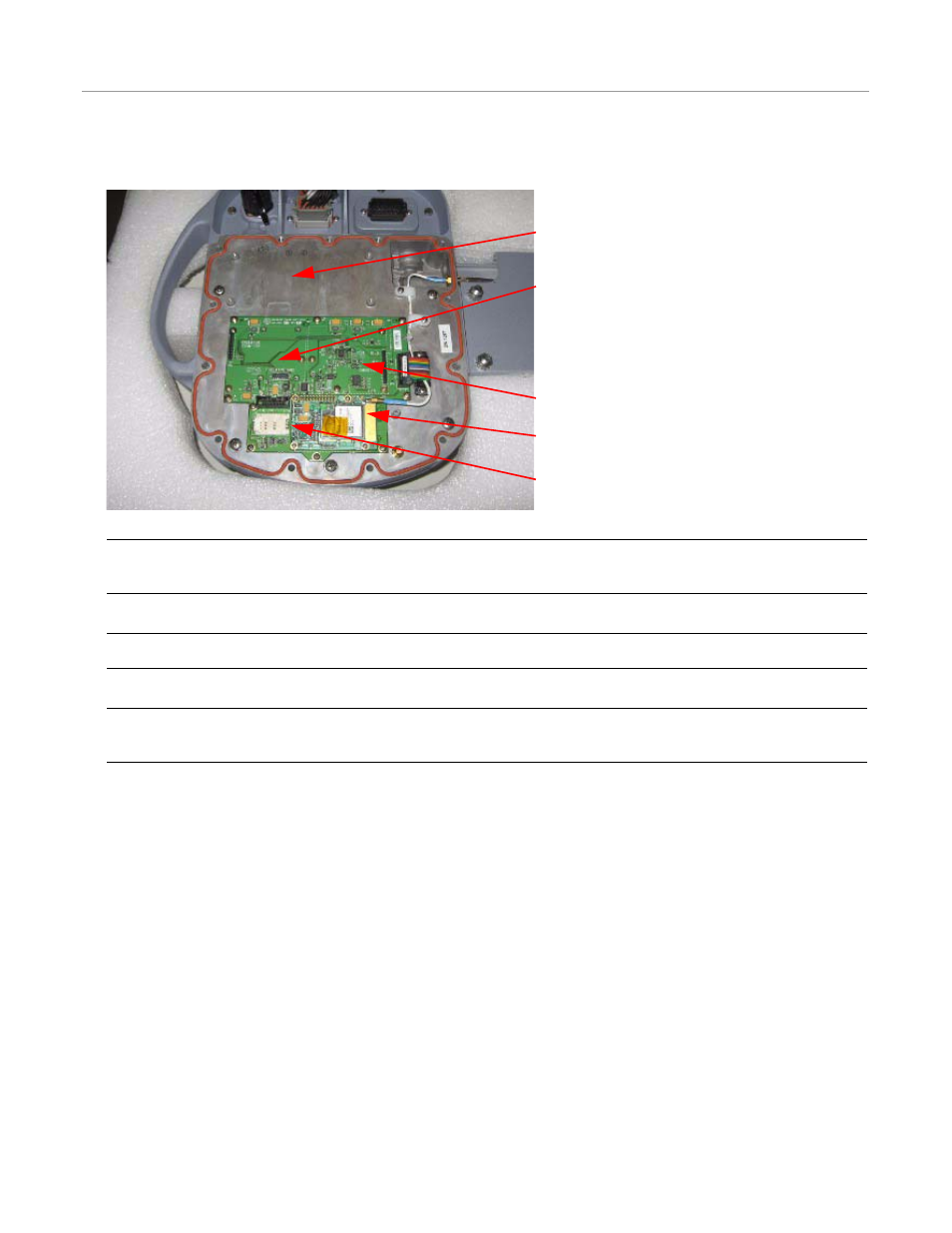
6. Remove the ParaDyme Smart Antenna bottom cover to access the component mounting locations.
Figure 4-4
Cover Removed and Component Mounting Locations Identified
Note: This figure shows only the Cell Modem installed. Depending on which options have been already installed,
your Roof Module may appear different than the figure.
Note: The Cell Modem installed in your ParaDyme may be different than the one shown in the figure.
Note: Always wear an electrostatic discharge wrist strap when handling a printed circuit board. Failure to use an
electrostatic discharge wrist strap may cause permanent damage to the printed circuit board and void the warranty.
7. Refer to one or more of the following sections for instructions on installing your kit or kits.
•
Changing or Installing a SIM Card on page 18
•
OmniSTAR Receiver Kit Installation Procedure (200-0504-02 Kit) on page 21
•
900 MHz RTK Radio Modem Kit Installation Procedure (200-0505-04 Kit) on page 24
•
UHF and VHF Radio Modem Kit Installation Procedure on page 32
UHF/VHF Radio Module Mounting Location
900 MHz Radio Module Mounting Location
OmniSTAR Module Mounting Location
Cell Modem Location
SIM Card Mounting Location
- Yield Monitor 2000 Operators Manual (202 pages)
- Yield Monitor 2000 Quick Reference Sheets (2 pages)
- PF3000 Harvest & Application Operators Manual (259 pages)
- PF3000 Cotton Yield Monitor Operators Manual (149 pages)
- PF3000/PF3000Pro Harvest Master Mode Operators Manual (13 pages)
- PF3000/PF3000Pro Advanced Light Bar Operators Manual (59 pages)
- PF3000/PF3000Pro Harvest Mode Quick Reference Sheets (2 pages)
- PF3000/PF3000Pro Cotton Harvest Quick Reference Sheets (2 pages)
- PF3000/PF3000Pro Site Verification Mode Quick Reference Sheets (2 pages)
- PF3000/PF3000Pro Rawson Accu-Rate Direct Drive Quick Reference Sheets (9 pages)
- PF3000/PF3000Pro Rawson and New Leader Controllers Quick Reference Sheets (4 pages)
- PF3000/PF3000Pro Raven Controllers (with serial port) Quick Reference Sheets (4 pages)
- PF3000/PF3000Pro Raven Controllers (without serial port) Quick Reference Sheets (3 pages)
- PF3000/PF3000Pro Mid-Tech Controllers Quick Reference Sheets (4 pages)
- PF3000/PF3000Pro Dickey-john Land Manager Quick Reference Sheets (4 pages)
- PF3000/PF3000Pro Dickey-john Seed Manager Quick Reference Sheets (3 pages)
- PF3000/PF3000Pro Hiniker 8100 and 8150 Controllers Quick Reference Sheets (3 pages)
- PF3000/PF3000Pro Hiniker 8605 Controller Quick Reference Sheets (4 pages)
- PF3000/PF3000Pro TeeJet 844 Controller Quick Reference Sheets (4 pages)
- PF3000/PF3000Pro Flexicoil Flex Control Quick Reference Sheets (4 pages)
- PF3000/PF3000Pro Microtrack MT9000/Hardi 3500 Controllers Quick Reference Sheets (4 pages)
- PF3000/PF3000Pro Krohne Flow Meter Quick Reference Sheets (3 pages)
- PF3000/PF3000Pro Shaft Speed Sensor Quick Reference Sheets (3 pages)
- PF3000Pro Harvest & Application Operators Manual (294 pages)
- PF3000Pro Cotton Yield Monitor Operators Manual (168 pages)
- PFadvantage Harvest & Application Operators Manual (264 pages)
- PFadvantage Cotton Yield Monitor Operators Manual (166 pages)
- InSight Harvest Mode (4 pages)
- InSight Site Verification Mode (4 pages)
- InSight Tillage Mode (8 pages)
- InSight Flow Meter (9 pages)
- InSight Spinner Spreader (14 pages)
- InSight Strip-Till (10 pages)
- InSight NORAC UC5 (4 pages)
- InSight Direct Injection (4 pages)
- InSight Rawson and New Leader Controllers (5 pages)
- InSight Raven Serial, NL Mark V, SP6 (5 pages)
- InSight Mid-Tech Controllers (5 pages)
- InSight Direct Command Liquid (19 pages)
- Integra DirectCommand Clutch Control Quick Reference Guides (1 page)
- InSight SC Hydraulic Seed Rate Control (4 pages)
- InSight SC Stepper Seed Rate Control (3 pages)
- InSight SC KINZE PMM (3 pages)
- InSight SC Seed Tube Monitor (STMM) (16 pages)
- InSight Ver.8.0 Users Manual (342 pages)