Ag Leader ParaDyme Radio Option Kits Hardware Installation Guide User Manual
Page 43
Hardware Installation Guide
37
UHF and VHF Radio Modem Kit Installation Procedure
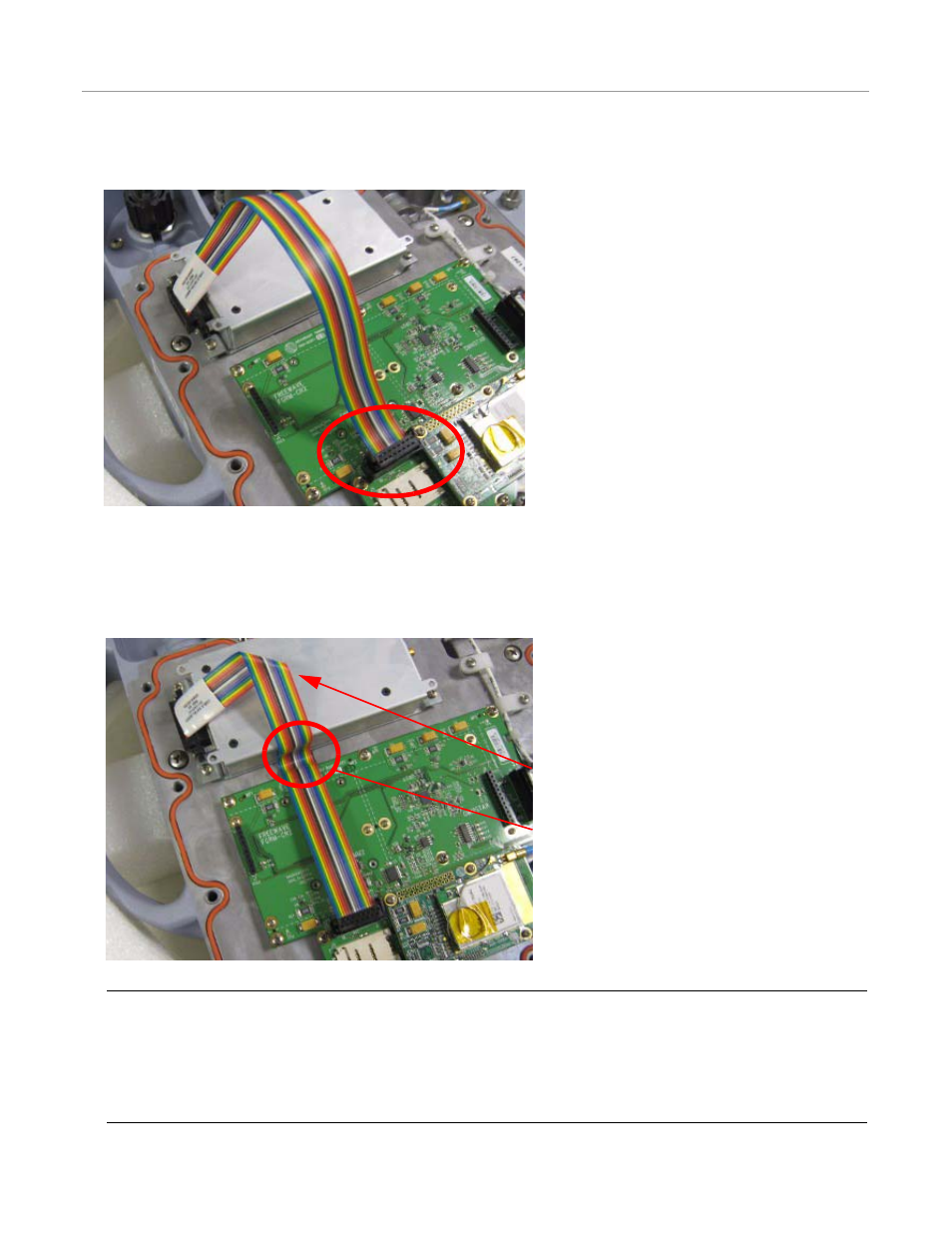
11. Connect the other end of the ribbon data cable to J6 connector on the circuit board as shown in Figure 4-38.
Figure 4-38 Data Cable Routing
12. There is a slight depression in the bottom of the ParaDyme casting between where the UHF or VHF radio and circuit board
are mounted. Carefully fold the ribbon cable down so that it touches the casting in this depression. Keep the ribbon cable
held down at the casting, and then fold it around the top part of the UHF or VHF radio. Finally, fold the ribbon cable at a 90
degree angle on top of the UHF or VHF radio as shown in Figure 4-40.
Figure 4-39 Ribbon Cable Arrangement
Note: When reattaching the bottom cover, there is a reinforcement wall molded into the cover between the circuit
board and the UHF or VHR radio mounting location with a slight gap to allow the ribbon cable to pass from one side
to the other. This is shown in Figure Figure 4-40. If the ribbon cable is not routed properly, it can be crushed or
broken when the cover is reattached. To prevent this type of damage, the ribbon cable must be folded and positioned
as shown in Figure 4-40. A piece of tape can be used to hold the ribbon cable in place on top of the UHF or VHF
radio until the cover is reattached.
90 Degree Fold
Casting Depression Location