Pdms, 31 dual pdu assembly – HP 4000.6000.8000 Enterprise Virtual Arrays User Manual
Page 81
Each of the two PDU power cables has an AC power source specific connector. The circuit
breaker-controlled PDU outputs are routed to a group of four AC receptacles (see
). The
voltages are then routed to PDMs, sometimes referred to as AC power strips, mounted on the two vertical
rails in the rear of the rack.
1
0130a
2
3
5
4
5
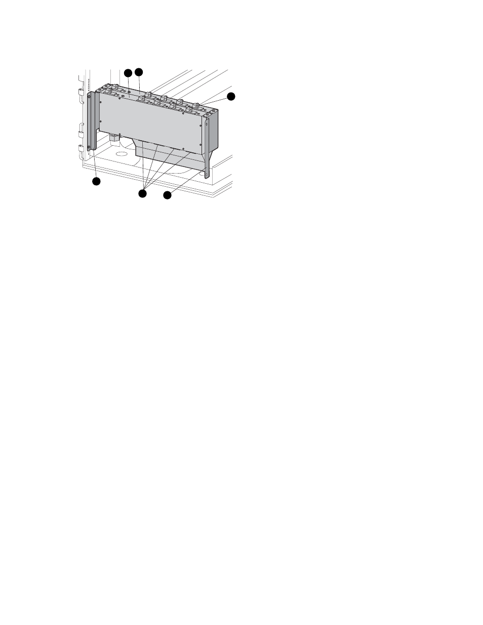
Figure 31 Dual PDU assembly
1. PDU 1
2. PDU 2
3. Circuit breakers
4. AC receptacles
5. Mounting hardware
PDU 1
PDU 1 connects to AC power distribution source 1. A PDU 1 failure:
•
Disables the power distribution circuit.
•
Removes power from PDMs 1, 2, and 3.
•
Disables PS 1 in the drive enclosures.
•
Disables the upper controller power supply.
PDU 2
PDU 2 connects to AC power distribution source 2. A PDU 2 failure:
•
Disables the power distribution circuit.
•
Removes power from PDMs 4, 5, and 6.
•
Disables PS 2 in the drive enclosures.
•
Disables the lower controller power supply.
PDMs
There are six PDMs mounted in the rear of each rack:
•
Three mounted on the left vertical rail connect to PDU 1.
•
Three mounted on the right vertical rail connected to PDU 2.
Each PDM has eight AC receptacles and one thermal circuit breaker. The PDMs distribute the AC power
from the PDUs to the enclosures. Two power sources exist for each controller pair and drive enclosure. If
a PDU fails, the system will remain operational.
4000/6000/8000 Enterprise Virtual Array user guide
81