Fibre channel loop switches, Power-on self test (post), Reading the switch indicators – HP 4000.6000.8000 Enterprise Virtual Arrays User Manual
Page 66: 22 fc loop switch
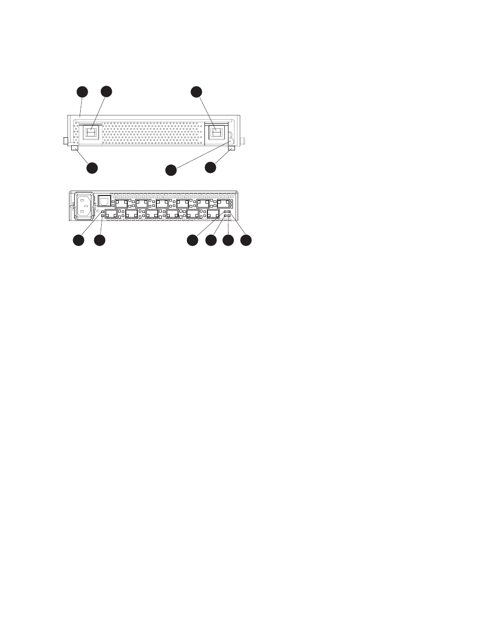
Fibre Channel loop switches
The EVA8000 uses four FC loop switches (
) to connect all of the drive enclosures to the
controller pair using FC cables. Each switch acts as a central point of interconnection and establishes a
fault-tolerant physical loop topology.
3
44
42
42
3
1
6
5
7
8
9
10
Figure 22 FC loop switch
1. Handle
2. Bezel snaps
3. Alignment tabs
4. Walk-up RS232 port
5. SFP status indicator
6. Port Bypassed indicator
7. POST fault indicator
8. Over Temp indicator
9. Power indicator
10. Loop operational indicator
Power-on self test (POST)
When you power on the Fibre Channel switch, it performs a Power–on Self Test (POST) to verify that
the switch is functioning properly. During a POST, all of the indicators turn on for approximately two
seconds. Then, turn off all of the indicators, except the power indicator.
If the Port Bypass indicators are blinking at a constant rate and the POST Fault indicator is on, the
switch detected a fault during the POST. In this case, you need to contact your HP authorized service
representative.
Reading the switch indicators
The Fibre Channel switch contains both system indicators and port indicators. The system indicators
indicate the status of the switch, and the port indicators provide status of a specific port.
shows
the Fibre Channel switch with the system and port indicators.
lists and describes the system indicators.
66
Enterprise Virtual Array hardware components